PLC, SCADA, Automation, PLC Programming, PLC eBook, Free PLC Training
Home
Donate
Download
Get Free PLC eBook
PLC Programming Examples
Contact Us
Privacy Policy
Follow Me
Home
Donate
Download
Get Free PLC eBook
PLC Programming Examples
Contact Us
Privacy Policy
Follow Me
Wednesday, August 5, 2009
Definition Function (MC) Master control and (MCR) Master Control Reset for PLC Keyence Programming
MC PLC Keyence : MC - Master Control. Purpose: Sets the master control relay. MCR PLC Keyence : MCR - Master Control Reset. ...
Simulation Make (MC) Master Control and (MCR) Master Control Reset for PLC Keyence
Example Ladder PLC Keyence Programming : Simulation Make (MC) Master Control and (MCR) Master Control Reset for PLC Keyence : ...
How to Work (MC) Master control and (MCR) Master Control Reset for PLC Keyence Programming
MC / MCR - PLC Keyence Programming How to Work (MC) Master control and (MCR) Master Control Reset With some Conditions : Condition 1 : ...
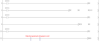
Definition Function (MC) Master control and (MCR) Master Control Reset PLC Mitsubishi Programming
MC PLC Mitsubishi : MC - Master Control. Purpose: After the execution of an MC instruction, the bus line (LD, LDI point) shifts to ...
Simulation Make (MC) Master Control and (MCR) Master Control Reset for PLC Mitsubishi
Example Ladder PLC Mitsubishi Programming : Simulation Make (MC) Master Control and (MCR) Master Control Reset PLC Mitsubishi : ...
How to Work (MC) Master control and (MCR) Master Control Reset for PLC Mitsubishi Programming
MC / MCR - PLC Mitsubishi Programming How to Work (MC) Master control and (MCR) Master Control Reset With some Conditions : Condition 1...
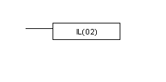
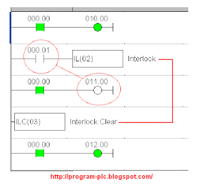
Definition Function (IL) Interlock and (ILC) Interlock Clear for PLC Omron Programming
IL PLC Omron : IL(02) - Interlock. Purpose: If an interlock condition is OFF, all outputs and all timer PVs between the current IL(...
Simulation Make (IL) Interlock and (ILC) Interlock Clear for PLC Omron
Example Ladder PLC Omron Programming : Simulation Make (IL) Interlock and (ILC) Interlock Clear PLC Omron : Please Download ...
How to Work (IL) Interlock and (ILC) Interlock Clear for PLC Omron Programming
IL / ILC - PLC Omron Programming How to Work (IL) Interlock and (ILC) Interlock Clear With some Conditions : Condition 1 : Input 000....
Tuesday, August 4, 2009
PLC Keyence Programming for Cutting Machine
PLC Type KV Keyence , Name Input / Output PLC : INPUT PLC : 0000 ; Push Button Start 0001 ...
Monday, August 3, 2009
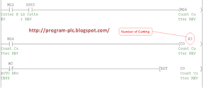
PLC Mitsubishi Programming for Cutting Machine
PLC Type FX-Mitsubishi , Name Input / Output PLC : INPUT PLC : X000 ; Push Button Start X001 ...
Sunday, August 2, 2009
PLC Omron Programming for Cutting Machine
PLC Type Series-C Omron , Name Input / Output PLC : INPUT PLC : 000.00 ; Push Button Start 000.01 ...
Newer Posts
Older Posts
Home
You may also like these ebook:
Get Free PLC eBook directly sent to your email,
and email subscription to program-plc.blogspot.com
We hate SPAM. Your information is never sold or shared with anyone.
Your Email Will Be 100% Secured !
Your email is stored safely on Google FeedBurner