Standard Sequence Programming for PLC Programming is the original made in program-plc.blogspot.com and FREE for You
Standard Sequence for PLC Programming consists of :
1. Input Condition
2. Trigger And Sensor Condition
3. Output Condition, And
4. Controller
The following is a diagram of the Input, Trigger, Output and Controller
 The following example the use of Standard Sequence Programming (Input, Trigger, Output and Controller) in ladder diagram :
 1. Example Input Condition
 Legend:
I-1 : Input Condition 1
I-2 : Input Condition 2
I-3 : Input Condition 3
O-4 : Output Condition 4
S-3 : Sensor 3
C-1 : Output Controller 1
PLC Input : PLC Input from PLC Hardware
2. Example Trigger And Sensor Condition
 Legend:
Tr : Trigger to Controller
C-1 : Output Controller 1
C-2 : Output Controller 2
C-3 : Output Controller 3
C-4 : Output Controller 4
S-1 : Sensor 1
S-2 : Sensor 2
S-3 : Sensor 3
S-4 : Sensor 4
I-2 : Input Condition 2
I-3 : Input Condition 3
STEP0 : Waiting Start = ON, Waiting All Origin = ON, etc.
STEP1 : Sequence 1
STEP2 : Sequence 2
STEP3 : Sequence 3
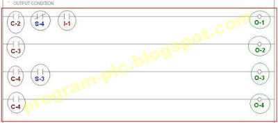
3. Example Output Condition
 Legend:
O-1 : Output Condition 1
O-2 : Output Condition 2
O-3 : Output Condition 3
O-4 : Output Condition 4
C-2 : Output Controller 2
C-3 : Output Controller 3
C-4 : Output Controller 4
S-3 : Sensor 3
S-4 : Sensor 4
I-1 : Input Condition 1
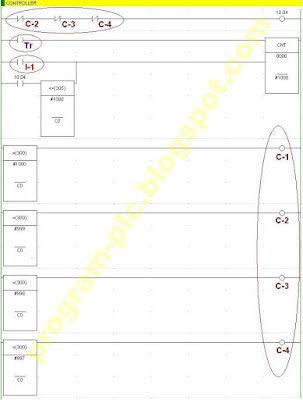
4. Example Controller
Legend:
Tr : Trigger from "2. Trigger And Sensor Condition"
C-1 : Output Controller 1
C-2 : Output Controller 2
C-3 : Output Controller 3
C-4 : Output Controller 4
I-1 : Input Condition 1
4.1. Controller for Siemens PLC
 4.2. Controller for Allen Bradley PLC
 4.3. Controller for Omron PLC
 4.4. Controller for Mitsubishi PLC
 4.5. Controller for Keyence PLC
 4.6. Controller for GE Fanuc PLC
Application for Standard Sequence Programming :
1. Simple Movement/Process :
--> PLC Control for 3 Movement
2. Complex Movement/Process :
--> PLC Control for Automatic Welding Machine
Standard Sequence for PLC Programming consists of :
1. Input Condition
2. Trigger And Sensor Condition
3. Output Condition, And
4. Controller
The following is a diagram of the Input, Trigger, Output and Controller
 The following example the use of Standard Sequence Programming (Input, Trigger, Output and Controller) in ladder diagram :
  1. Example Input Condition
  Legend:
I-1 : Input Condition 1
I-2 : Input Condition 2
I-3 : Input Condition 3
O-4 : Output Condition 4
S-3 : Sensor 3
C-1 : Output Controller 1
PLC Input : PLC Input from PLC Hardware
2. Example Trigger And Sensor Condition
 Legend:
Tr : Trigger to Controller
C-1 : Output Controller 1
C-2 : Output Controller 2
C-3 : Output Controller 3
C-4 : Output Controller 4
S-1 : Sensor 1
S-2 : Sensor 2
S-3 : Sensor 3
S-4 : Sensor 4
I-2 : Input Condition 2
I-3 : Input Condition 3
STEP0 : Waiting Start = ON, Waiting All Origin = ON, etc.
STEP1 : Sequence 1
STEP2 : Sequence 2
STEP3 : Sequence 3
3. Example Output Condition
 Legend:
O-1 : Output Condition 1
O-2 : Output Condition 2
O-3 : Output Condition 3
O-4 : Output Condition 4
C-2 : Output Controller 2
C-3 : Output Controller 3
C-4 : Output Controller 4
S-3 : Sensor 3
S-4 : Sensor 4
I-1 : Input Condition 1
4. Example Controller
Legend:
Tr : Trigger from "2. Trigger And Sensor Condition"
C-1 : Output Controller 1
C-2 : Output Controller 2
C-3 : Output Controller 3
C-4 : Output Controller 4
I-1 : Input Condition 1
4.1. Controller for Siemens PLC
 4.2. Controller for Allen Bradley PLC
 4.3. Controller for Omron PLC
 4.4. Controller for Mitsubishi PLC
 4.5. Controller for Keyence PLC
 4.6. Controller for GE Fanuc PLC
Application for Standard Sequence Programming :
1. Simple Movement/Process :
--> PLC Control for 3 Movement
2. Complex Movement/Process :
--> PLC Control for Automatic Welding Machine
