This article will describe to the Allen Bradley Micrologix PLC (1100 or 1400) user who wishes to connect to an EtherMeter using the Ethernet/IP protocol. When creating an Ethernet/IP client/server connection between an Allen Bradley Micrologix 1100 or 1400 PLC (client) and an EtherMeter (server), no special set up is generally required within the EtherMeter’s set up menu. The EtherMeter features an ‘always on’ Ethernet/IP server on TCP logical port 44818 and it is configured to auto detect and service incoming client requests from MicroLogix 1100 and 1400 PLC’s. To simplify integration into an Ethernet/IP network, the EtherMeter emulates a SLC/500 series PLC.
1. Wiring Configuration.
In this example, the Ethernet ports on the MicroLogix and EtherMeter are wired directly to each other, without an Ethernet switch, using a single Ethernet crossover cable. Alternatively, the Ethernet ports of both the MicroLogix and EtherMeter could be connected to a common Ethernet switch if expanded network connectivity is desired.
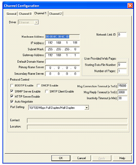
2. MicroLogix Ethernet Port (Port 1) Configuration.
Within a MicroLogix PLC, communication setup is performed within the RsLogix Programming environment. To begin the setup, a new programming project should be initialized in RsLogix using the appropriate selections for processor type, version, and serial port setup. For brevity, the details of these steps have been omitted.
It is important to note that the default static IP address of the EtherMeter is 192.168.1.140.

Labels:
Allen Bradley PLC
Allen Bradley PLC