In Rung 0, a self resetting, one second timer is created to setup the polling interval, although a shorter or longer polling interval could be selected, depending upon the application.
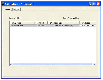
In Rung 1, the one second timer is used to trigger the message instruction to the EtherMeter. A double left click on the “Setup Screen” button of the MSG Block causes a popup window to appear.
Within the popup window, first the general tab should be selected, and the parameters on its page should be entered as instruction.
Under the “This Controller” heading, note that the selected channel is “Channel 1 (Integral)”, which corresponds to the MicroLogix’s Ethernet port. The Selected “Communication Command” is “500CPU read”, as the EthernetMeter an S:C/500.The selected target data table address within the MicroLogix is N7:0, although a different memory location could be chosen. The “Size in Elements” is entered as “8” (8 x 16 bit words).
Under the “Target Device” heading, note that the “Data Table Address” is entered as N7:0, as this is the desired beginning memory location within the EtherMeter. For the completed memory map of the EtherMeter. “Local” should be selected. For routing file, R110:0 is entered, although an alternate Routing Information file could be chosen.
