For this application, I use Omron PLC CP1L with external
analog input and digital output as digital battery level indicator with 4 levels
for 6 volt battery.
C. 6 volt and 4 levels battery indicator to digitized
Download PLC Program File: Click Here
F. Video about make ladder program for Battery Level Indicator
See the video for this application:
A. Wiring
Diagram between Battery, Analog Input PLC, and Digital Output PLC of Omron PLC
CP1L
A.1.Preparation
1. Omron PLC CP1L-L10 with external analog input
2. External Analog
Cable
Remarks:
Black color to negative battery
White color to positive batteryy
3. Battery DC 6 Volt for Testing
For this application, I use battery dc 1.5 volt as
many as 4 pieces.
A.2. Installation
1. Battery to Analog
Input PLC
2. Accumulator to Analog Input PLC
B.
Information about External Analog Input of Omron PLC CP1L
Analog voltage values 0 volts to 10 volts can be
digitized with 0 to 255. Digitized values are sent to the A643 of Omron PLC CP1L.
The following is relationship between Voltage Values and A643.
C. 6 volt and 4 levels battery indicator to digitized
The following descriptions:
1.
10 Volt digitized = 255
2. 6
Volt digitized = (255/10) X 6 = 153
3. 6
Volt per 4 Levels (Per Level) digitized = 153/4 = 38.25
In PLC Programming: Because per Level there is 2 digits after
point, and then 153 multiplied by 100. And Value for per Level = (153 X 100) /
4 = 15300 / 4 = 3825 (this value no point and suitable for PLC programming)
4. The values of each level become:
4. a. Level 1: (153 X 100)/4 = 3825 is the digital
value of analog 1.5 Volt of battery
4. b. Level 2: (153 X 100)/3 = 7650 is the digital
value of analog 3 Volt of battery
4. c. Level 3: (153 X 100)/2 = 34425 is the digital
value of analog 4.5 Volt of battery
4. d. Level 4: (153 X 100)/1 = 15300 is the digital
value of analog 6 Volt of battery
5.
PLC Programming for per levels of Battery Level Indicator
5. a. BufferA643 = A643 X 100
5. b. Level 1: If (BufferA643) >= 3825) Then Digital
Output 100.00 = ON
5. c. Level 2: If (BufferA643) >= 7650) Then Digital
Output 100.01 = ON
5. d. Level 3: If (BufferA643) >= 34425) Then Digital
Output 100.02 = ON
5. e. Level 4: If (BufferA643) >= 15300) Then Digital
Output 100.03 = ON
The following is relationship between battery level
indicator and Digital Value (A643) of Omron PLC CP1L.
D. Digital Output
Light Lit for each Level
E. Ladder Program for Battery Level Indicator
F. Video about make ladder program for Battery Level Indicator
G. For other
battery voltage
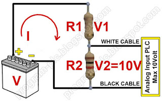
Battery voltage greater than 10 volt should use
additional resistors, e.g. 12VDC, etc.
In this case use Kirchhoff's Voltage Law (KVL), See
the picture below:
Example
Battery Voltage (V) =12volt
Defined:
V=12 volt
R2=1000 ohm
V2=10 volt
Then:
I=V / (R1+R2)
I=V2/R2
V2/R2 =V / (R1+R2)
V2(R1+R2)=V*R2
V2*R1+V2*R2=V*R2
V2*R1=V*R2 – V2*R2
R1=
((V-V2)*R2)/V2
R1=((12-10)*1000)/10
R1=2000/10
R1=200 ohm
Watt Resistor (Standards: 1/8W, 1/4W, 1/2W, etc.)
I=V/(R1+R2)
I=12/(200+1000)
I=0.01A
Watt R1=I*I*R1=0.01*0.01*200
= 0.02watt = 1/8W
Watt R2 =I*I*R2=0.01*0.01*1000=0.1watt
= 1/4W
For Battery Voltage=12volt uses R1=200 ohm 1/8W and
R2=1000 ohm 1/4W
For other battery voltage, you can try with way the
above.


