Video about the testing of Modbus communication between CNC and PLC using Mach3 CNC Software
A. Preparation for this application:
1. Free Download Mach3 CNC Software (click here) or http://www.machsupport.com/downloads.php and choose Lockdown
2. PLC Cable for Siemens S7-200 PLC
3. Siemens S7-200 PLC
4. Connect PLC Cable to Port 0 in Siemens S7-200 PLC
B. Modbus and Ladder Program in the PLC
Download PLC program (click here) and Upload to PLC. Or creating a ladder program as shown below and upload them to the PLC.
1. Definition of ladder program for Network 1:
Assigns Port:
Mode =0 =>assigns port 0 to PPI and disable Modbus protocol
Mode = 1 => assigns port 0 to Modbus protocol and enables the Modbus protocol
Modbus Communication Setting in PLC:
Modbus Address Slave: 1 (Addr) =>Addr Values between 1 and 247
Modbus Baud Rate: 9600 (Baud) => Baud rate at 1200,2400,4800,9600,19200,38400,57600,115200
Modbus Parity: None (Parity = 0) => None Parity = 0, Odd Parity = 1, Even Parity = 2
Modbus Message Timeout: 20 (Delay)
Input, Output, Analog Setting:
MaxIQ: 128 => Number of I and Q Points available to Modbus Addresses (Value of 0 to 128). For disables MaxIQ=0.
MaxAI: 32 => 0 for CPU 221, 16 for CPU 222 and 32 for CPU 224, 224XP, 226, 226XM
Memory setting in PLC:
Input / Output Memory (Register) Holding, starting from: VB800 (HoldSt~)
Maximum Memory (Register) Holding: 100 (MaxHold) => Access the 100 Words of V memory Or 200 Bytes of V memory.
2. Definition of ladder program for Network 3 and Network 4:
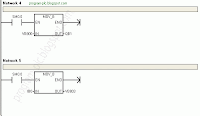
Network 3: Move Byte from VB801 to QB0 (Q0.0 to Q0.7)
Network 4: Move Byte from VB800 to QB1 (Q1.0 to Q1.7)
3. Definition of ladder program for Network 5 and Network 6:
Network 5: Move Byte from IB0 (I0.0 to I0.7) toVB803
Network 6: Move Byte from IB1 (I1.0 to I1.7) to VB802
C. Modbus and Mach3 CNC Software
Config Ports and Pins:
Modbus Plugin Setting:
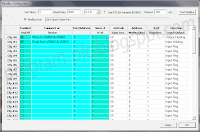
1. Modbus Communication Setting
Port Num: 3
Baud Rate: 9600
Data: 8 – 1 – N
2. Modbus Register Setting
2.1. Cfg #0:
Slave #: Address Slave Number in PLC (Addr = 1)
Direction: Output-Holding => Write from Mach3 to V memory PLC
2.2. Cfg #1:
Slave #: Address Slave Number in PLC (Addr = 1)
Direction: Input-Holding => Read from V memory PLC to Mach3
2.3. Address Modbus(Var) and # of Registers:
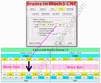
3. Modbus Access with Brains Mach3 CNC Software
Or download Brains file (click here) and Copy Paste to folder ...\Mach3\Brains , or default install Copy Paste to folder C:\Mach3\Brains
Brains View for Modbus Communication between PLC and Mach3 CNC
3.1. How to access the PLC Output with Modbus
Example:Write to PLC Output Q0.4
3.2. How to access the PLC Inputwith Modbus
Example:Read from PLC Input I0.1
A. Preparation for this application:
1. Free Download Mach3 CNC Software (click here) or http://www.machsupport.com/downloads.php and choose Lockdown
2. PLC Cable for Siemens S7-200 PLC
3. Siemens S7-200 PLC
4. Connect PLC Cable to Port 0 in Siemens S7-200 PLC
B. Modbus and Ladder Program in the PLC
Download PLC program (click here) and Upload to PLC. Or creating a ladder program as shown below and upload them to the PLC.
1. Definition of ladder program for Network 1:
Assigns Port:
Mode =0 =>assigns port 0 to PPI and disable Modbus protocol
Mode = 1 => assigns port 0 to Modbus protocol and enables the Modbus protocol
Modbus Communication Setting in PLC:
Modbus Address Slave: 1 (Addr) =>Addr Values between 1 and 247
Modbus Baud Rate: 9600 (Baud) => Baud rate at 1200,2400,4800,9600,19200,38400,57600,115200
Modbus Parity: None (Parity = 0) => None Parity = 0, Odd Parity = 1, Even Parity = 2
Modbus Message Timeout: 20 (Delay)
Input, Output, Analog Setting:
MaxIQ: 128 => Number of I and Q Points available to Modbus Addresses (Value of 0 to 128). For disables MaxIQ=0.
MaxAI: 32 => 0 for CPU 221, 16 for CPU 222 and 32 for CPU 224, 224XP, 226, 226XM
Memory setting in PLC:
Input / Output Memory (Register) Holding, starting from: VB800 (HoldSt~)
Maximum Memory (Register) Holding: 100 (MaxHold) => Access the 100 Words of V memory Or 200 Bytes of V memory.
2. Definition of ladder program for Network 3 and Network 4:
Network 3: Move Byte from VB801 to QB0 (Q0.0 to Q0.7)
Network 4: Move Byte from VB800 to QB1 (Q1.0 to Q1.7)
3. Definition of ladder program for Network 5 and Network 6:
Network 5: Move Byte from IB0 (I0.0 to I0.7) toVB803
Network 6: Move Byte from IB1 (I1.0 to I1.7) to VB802
C. Modbus and Mach3 CNC Software
Config Ports and Pins:
Modbus Plugin Setting:
1. Modbus Communication Setting
Port Num: 3
Baud Rate: 9600
Data: 8 – 1 – N
2. Modbus Register Setting
2.1. Cfg #0:
Slave #: Address Slave Number in PLC (Addr = 1)
Direction: Output-Holding => Write from Mach3 to V memory PLC
2.2. Cfg #1:
Slave #: Address Slave Number in PLC (Addr = 1)
Direction: Input-Holding => Read from V memory PLC to Mach3
2.3. Address Modbus(Var) and # of Registers:
Video About How to Modbus Setup in Mach3 CNC Software
3. Modbus Access with Brains Mach3 CNC Software
Video about How to Create Brains in Mach3 CNC for PLC Output/Input Access with Modbus Protocol
Or download Brains file (click here) and Copy Paste to folder ...\Mach3\Brains , or default install Copy Paste to folder C:\Mach3\Brains
Brains View for Modbus Communication between PLC and Mach3 CNC
3.1. How to access the PLC Output with Modbus
Example:Write to PLC Output Q0.4
3.2. How to access the PLC Inputwith Modbus
Example:Read from PLC Input I0.1


