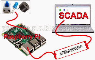
SCADA and Raspberry Pi Application, for SCADA use Free SCADA IGSS and Raspberry Pi use Raspberry Pi 2.
This application use MODBUS TCP/IP Communication between SCADA and Raspberry Pi.
I use wireless router for connection between Computer/SCADA and raspberry pi. In Raspberry Pi using Ethernet port connect to LAN port on a router, and computer connect to the router via WIFI/wireless.
Video about SCADA and Raspberry Pi 2
What is needed for this application?
1. Raspberry Pi 2
2. Wireless Router with LAN ports
3. Internet connection for software installation on a Raspberry Pi
4. Ethernet cable with RJ45 connector for connection between raspberry pi and router
5. Power Supply 5V with Micro USB for raspberry pi power
6. Micro SD Card for raspbian OS
7. Buzzer 5V
8. LED
9. Switch
10.Resistor 10K and 150
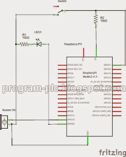
Hardware Connection for SCADA and Raspberry Pi Application:
Download Project File:
1. Free SCADA Software: http://igss.schneider-electric.com/products/igss/download/free-scada.aspx
2. SCADA file project, click here
3. Raspberry Pi file project, click here
Software installation on a Raspberry Pi:
STEP 1:
Copy Paste All Project file to folder /home/pi on Raspberry Pi 2
STEP 2:
Raspberry Pi connect to Internet.
In LXTerminal:
sudo apt-get install python-pymodbus python-twisted-conch
STEP 3:
In LXTerminal
type sudo crontab -e
Scroll to bottom and add:
@reboot python /home/pi/startup.py
Ctrl+X to exit, Y to save followed by enter twice
STEP 4:
In LXTerminal
sudo reboot
Video about SCADA and Raspberry Pi Setup:
SCADA Configuration:
1. Go to System Configuration - MODBUS/TCP driver - 7TMODTCP - Node 0 - Node Properties
2. In Node Properties - set Remote IP Address:
my raspberry pi has the IP address 192.168.0.105 and then remote IP Address is set to 192.169.0.105
Python Code:
Remote IP Address for Raspberry Pi Number 2 is 192.168.0.106
Edit Mapping with Node 1 for Raspberry Pi Number 2
This application use MODBUS TCP/IP Communication between SCADA and Raspberry Pi.
I use wireless router for connection between Computer/SCADA and raspberry pi. In Raspberry Pi using Ethernet port connect to LAN port on a router, and computer connect to the router via WIFI/wireless.
Video about SCADA and Raspberry Pi 2
What is needed for this application?
1. Raspberry Pi 2
2. Wireless Router with LAN ports
3. Internet connection for software installation on a Raspberry Pi
4. Ethernet cable with RJ45 connector for connection between raspberry pi and router
5. Power Supply 5V with Micro USB for raspberry pi power
6. Micro SD Card for raspbian OS
7. Buzzer 5V
8. LED
9. Switch
10.Resistor 10K and 150
Hardware Connection for SCADA and Raspberry Pi Application:
Download Project File:
1. Free SCADA Software: http://igss.schneider-electric.com/products/igss/download/free-scada.aspx
2. SCADA file project, click here
3. Raspberry Pi file project, click here
Software installation on a Raspberry Pi:
STEP 1:
Copy Paste All Project file to folder /home/pi on Raspberry Pi 2
STEP 2:
Raspberry Pi connect to Internet.
In LXTerminal:
sudo apt-get install python-pymodbus python-twisted-conch
STEP 3:
In LXTerminal
type sudo crontab -e
Scroll to bottom and add:
@reboot python /home/pi/startup.py
Ctrl+X to exit, Y to save followed by enter twice
STEP 4:
In LXTerminal
sudo reboot
Video about SCADA and Raspberry Pi Setup:
SCADA Configuration:
1. Go to System Configuration - MODBUS/TCP driver - 7TMODTCP - Node 0 - Node Properties
2. In Node Properties - set Remote IP Address:
my raspberry pi has the IP address 192.168.0.105 and then remote IP Address is set to 192.169.0.105
Python Code:
from pymodbus.server.async import StartTcpServer
from pymodbus.datastore import ModbusSequentialDataBlock
from pymodbus.datastore import ModbusSlaveContext, ModbusServerContext
from twisted.internet.task import LoopingCall
import RPi.GPIO as GPIO
LED=26
BZ=19
SW=21
GPIO.setmode(GPIO.BCM)
GPIO.setwarnings(False)
GPIO.setup(LED,GPIO.OUT)
GPIO.setup(BZ,GPIO.OUT)
GPIO.setup(SW, GPIO.IN, pull_up_down=GPIO.PUD_UP)
GPIO.output(LED, GPIO.LOW)
GPIO.output(BZ, GPIO.HIGH)
store = ModbusSlaveContext(
di = ModbusSequentialDataBlock(0, [0]*100),
co = ModbusSequentialDataBlock(0, [0]*100),
hr = ModbusSequentialDataBlock(0, [0]*100),
ir = ModbusSequentialDataBlock(0, [0]*100))
context = ModbusServerContext(slaves=store, single=True)
def updating_writer(a):
context = a[0]
register = 3
slave_id = 0
address = 0
values = [1]
if GPIO.input(SW):values = [0]
context[slave_id].setValues(register,address,values)
print values
def read_context(a):
context = a[0]
register = 3
slave_id = 0
address = 10
value = context[slave_id].getValues(register,address,10)
if value[0]==0:GPIO.output(LED, GPIO.LOW)
if value[0]==1:GPIO.output(LED, GPIO.HIGH)
if value[1]==0:GPIO.output(BZ, GPIO.LOW)
if value[1]==1:GPIO.output(BZ, GPIO.HIGH)
print value[0]
print value[1]
read = LoopingCall(f=read_context, a=(context,))
read.start(.2)
write = LoopingCall(f=updating_writer, a=(context,))
write.start(.2)
StartTcpServer(context)
For Two Raspberry Pi
System Configuration Setting of SCADA Software:
Remote IP Address for Raspberry Pi Number 1 is 192.168.0.105
Remote IP Address for Raspberry Pi Number 2 is 192.168.0.106
Definition Setting of SCADA Software:
Edit Mapping with Node 0 for Raspberry Pi Number 1
Edit Mapping with Node 1 for Raspberry Pi Number 2
Labels:
Modbus
ModBus Communication
ModBus RTU
ModBus RTU Communication
Modbus TCP
Raspberry Pi
SCADA
SCADA and Raspberry Pi
SCADA Application
Modbus
ModBus Communication
ModBus RTU
ModBus RTU Communication
Modbus TCP
Raspberry Pi
SCADA
SCADA and Raspberry Pi
SCADA Application


