In PLC there are two kind input/output, there are Digital and analog. Digital input/output only have two condition TRUE and FALSE, or ENERGIZE and DE-ENERGIZE. In field this defined as ON and OFF.
Different with Digital, analog input/output not read True and False. Analog input/output read data changes linearly. In Field instrument like sensor, transmitter, receiver, they produce voltage from 0 – 24 V (maximum voltage can be different depend specification). Voltage changes from 0 -24 v can read by PLC trough Analog Input/output.
In this part, we will simulates the analog input and output PLC Programming with Simatic S7-PLCSim. Please follow the step by step to simulate Analog input/output programming in Simatic S7-PLCSim.
Step 1: Open Simatic Manager and Create New Project.
Follow Step 1 to Step 3 of the article about
Learning PLC Programming With SIMATIC S7-PLCSIM
Step 2: Adding CPU, Analog Input and Analog Output.
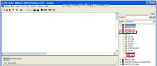
Select the Processor/CPU, Analog Input and Output module are used in Project. Double click on
Hardware and
HW Config window will be open.
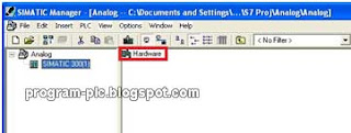 |
| Figure 1 Open HW Config |
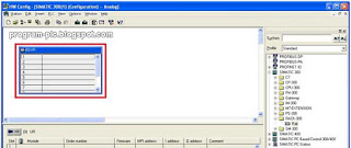
Expand the Simatic 300, in Folder Rack 300 select Rail and Drag into left Panel.
 |
| Figure 2 HW Config Window and add Rack |
In left panel, will show a Rack Column. This Rack Column represent a rail in Simatic 300 station, we can put Power Supply, CPU, Input and Output Module in this Rail.
 |
| Figure 3 Rail for Power Supply, CPU, Input and Output Module |
Open CPU-300 folder, and choose the CPU which will used in Project. In this case I use CPU 312. Select the CPU-312 and drag into Rack Column no 2. Number in Rack Column is represent the order each module in Rail.
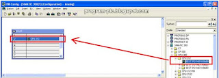 |
| Figure 4 Add CPU into Rail |
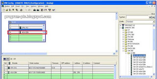
Open folder SM-300, in this folder we can choose AI, AO that we need. Open folder AI-300 and select SM 331 AI 2 x 12 Bit. Drag into Rack Column. This represent the Analog Input Module SM 331 with 2 Input analog and 12 Bit data buffer. In Rack Column below, that showing another information. That are I Address, this default analog Input address.
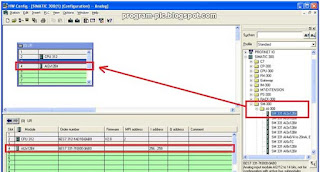 |
| Figure 5 Adding Analog Input Module |
Double click on AI2x12Bit module, AI module window properties will appear,
 |
| Figure 6 Double Click AI Module |
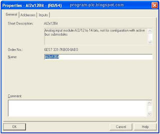
AI Module window properties show description for Analog Input module. In general tab, show the information for AI type.
 |
| Figure 7 General Description |
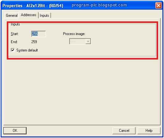
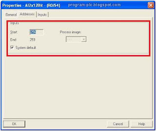
Click Address Tab. In this tab, show information for Input Address. The address is default but we can change the address, un-check the System default Box and change the address as needed.
 |
| Figure 8 Address |
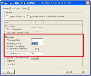
Click Input Tab. In this tab we can set the type for input, input can be Current or Voltage. And the range to be measured. In this project we choose the Voltage Input with range +/- 10V. Click
OK for save all changes.
 |
| Figure 9 Input Tab |
Step add AO module same with add AI module, expand SM-300 folder then open AO-300, select and drag SM 332 AO2x12Bit into Rack Column.
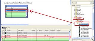 |
| Figure 10 Add AO Module |
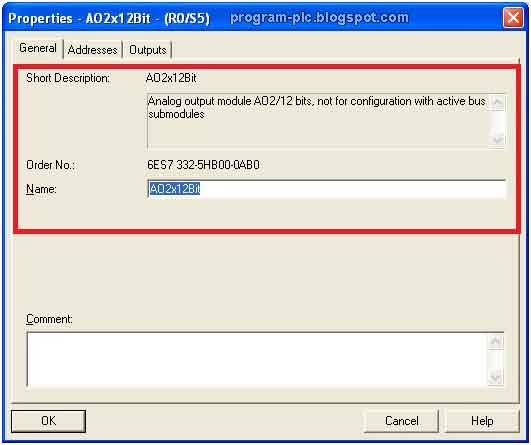
Double click again in AO module, to open AO Module Properties window. In General Tab properties, show general information for the AO Module.
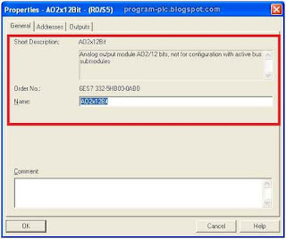 |
| Figure 11 AO General Properties |
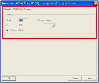
In address tab, show about address information for output. Same with AI, AO have default Address and we can change the default address with un-check the System default box.
 |
| Figure 12 AO Address Properties |
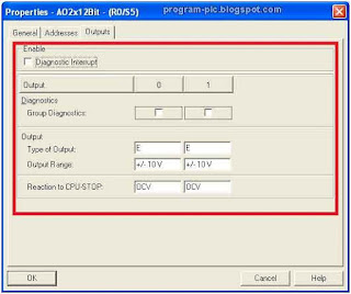
Output Tab properties, show the configuration for the output, we can choose the output we needed for the project. In this project we select voltage for output with range +/- 10 V.
 |
| Figure 13 Output properties |
After finish configure click save and compile for save and apply all changes.
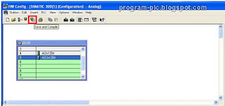 |
| Figure 14 Save and Compile |
Step 3: Configure Network
Click on NetPro icon to open NetPro window,
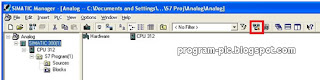 |
| Figure 15 Open NetPro |
In NetPro window, we can see a station. This station represent the station we create in this project. Click the MPI port (Highlighted in Figure 16) and drag to MPI network in above. Save and compile for save all changes.
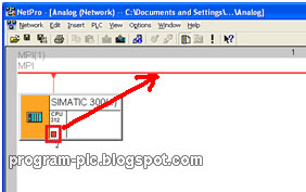 |
| Figure 16 Connect MPI Port |
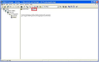
Step 4: PLC Programming Language
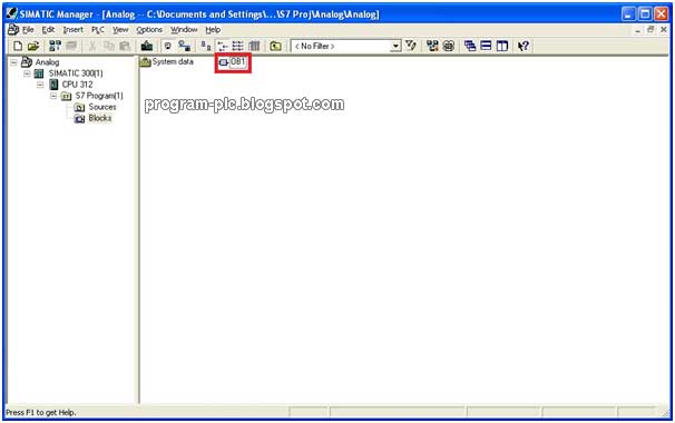
Double click on
OB1 Symbol in
Simatic manager window, dialog box Properties – Organization Block will appear select the language will use for programming.
 |
| Figure 17 OB1 Symbol for Open Program Block |
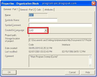 |
| Figure 18 Organization Block Properties Dialog Box |
Step 5: Ladder Programming for Move Data from AI to AO
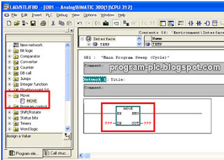
First we try to read analog input and Move to analog output, for do this we use
Move Instruction in Simatic manager. In left pane (Library) open Move folder, select
Move Instruction and drag into main pane.
 |
| Figure 19 Move Instruction |
MOVE (Assign a Value) is activated by the Enable
EN Input. The value specified at the
IN input is copied to the address specified at the
OUT output.
ENO has the same logic state as
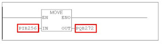
EN. MOVE can copy only BYTE, WORD, or DWORD data objects. User-defined data types like arrays or structures have to be copied with the system function "BLKMOVE". Put analog input address in
IN, analog output in
OUT. For assigning Input and output in program use forma PIB (in Byte), PIW (in Word). And PQB (in Byte), PQW (in Word).
 |
| Figure 20 Addressing |
Try to simulate program use Simatic S7-PCSim, run Simatic S7-PLCSim with click Simatic S7-PLCSim icon.
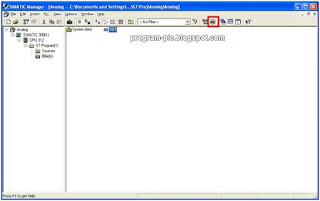 |
| Figure 21 Open Simatic S7-PLCSim |
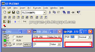 |
| Figure 22 Input Address in S7-PLCSim |
Put analog input address and analog output address in input and output variable on S7-PLCSim. For PIB use Slider, so we can change data linearly. For output we can’t measure the real output from AO, in S7-PLCSim the output from AO is in DATA. We can select data form in Binary, Word, Dword, Hexadecimal.
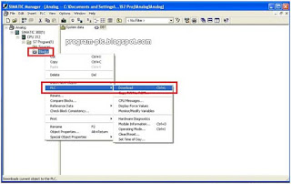 |
| Figure 23 Download Program |
Run S7-PCSim,
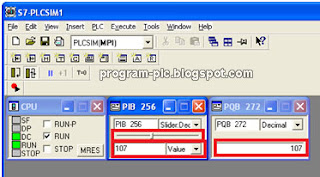 |
| Figure 24 Run PLCSim |
Move the slider in PIB 256, and see the change in PQB 272. In PLCSim we can measure voltage output from AO Module, the output is in data (Binary, Word, DWord, INT, Decimal, etc.).
Step 6: Store Data into memory
Same with previous step, but in this step we store data from Analog into Memory. We still use Move instruction. Open again Program Object, double click on OB1.
|
Figure 25 Open Program Block
|
Change address in Out become MB 1, this mean memory with address 1 with binary type data. Save and close program Block.
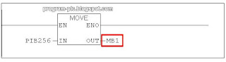 |
| Figure 26 Move data into memory |
Download again program into PLC, in PLCSim change Output Variable PQB 272 become MB 1.
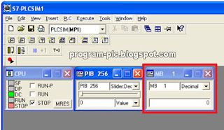 |
| Figure 27 PLCSIm Read Data from Memory |
Like in Step 4, try move the slider in PIB and see the changes in MB 1. This represent Analog Input Module read analog data from Field instrument and stored in memory.
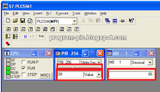 |
| Figure 28 Simulation store data into Memory |
Download project file
click here
Video Demonstration: https://www.youtube.com/watch?v=6oDBcr0tSok