PLC, SCADA, Automation, PLC Programming, PLC eBook, Free PLC Training
Home
Donate
Download
Get Free PLC eBook
PLC Programming Examples
Contact Us
Privacy Policy
Follow Me
Home
Donate
Download
Get Free PLC eBook
PLC Programming Examples
Contact Us
Privacy Policy
Follow Me
Tuesday, July 7, 2009
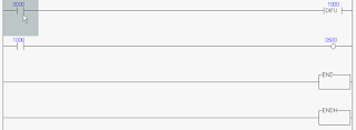
Definition Function DIFU or PLS PLC Programming
DIFU PLC Omron : DIFU(13) - Differentiate Up. Purpose: DIFU(13) turns ON the designated bit (B) for one scan on reception of the le...
Simulator DIFU PLC or PLS PLC
See Animation DIFU PLC or PLS PLC Please Download for see Animation DIFU PLC or PLS PLC : Please Click : Simulator DIFU PLC or PLS ...
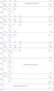
PLC Keyence Programming for Sorter Machine
Reading PLC Programming for Sorter Machine : Step 1 : If 0000=ON And 0001=OFF And 0002=OFF Then 1000=ON. Step 2 : If 0000=ON...
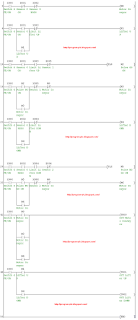
PLC Mitsubishi Programming for Sorter Machine
Reading PLC Programming for Sorter Machine : Step 1 : If X000=ON And X001=OFF And X002=OFF Then M0=ON. Step 2 : If X000=ON A...
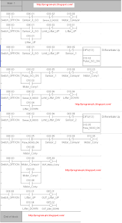
PLC Omron Programming for Sorter Machine
Reading PLC Programming for Sorter Machine : Step 1 : If 000.00=ON And 000.01=OFF And 000.02=OFF Then 010.00=ON. Step 2 : If...
Sunday, July 5, 2009
Thickness Detection Sensor
Example Type Thickness Detection Sensor for Detection Goods ( GO , NOGO ) Specifications Thickness Detection Sensor with 2 output ...
Goods Sensor or Proximity
Example Type Goods Sensor or Proximity to Detect there are not of Object To : PLC Programming for Sorter Machine
Wednesday, July 1, 2009
Makes Ladder PLC at Software PLC
Makes Ladder PLC at Software PLC Omron : See Animation Makes Ladder PLC Omron Please Download for see Animation Makes Ladder PLC O...
Newer Posts
Older Posts
Home
You may also like these ebook:
Get Free PLC eBook directly sent to your email,
and email subscription to program-plc.blogspot.com
We hate SPAM. Your information is never sold or shared with anyone.
Your Email Will Be 100% Secured !
Your email is stored safely on Google FeedBurner