A huge deal of switching control and control of analog I/O ports is required in a system of PLC. A model of FPGA is EP1K3OTC2O8-3 with 208 pins is utilized to construct maximum switching ports of I/O of 147. Since the system is expanded by bus of ARM, the ports of I/O FPGA are handled since if they just I/O ports of ARM itself. Figure below is a basic schematic diagram of link between ARM and FPGA.
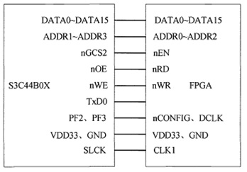
In figure above, the address lines and data lines of ARM are linked correspondingly with FPGA's. Every FPGA storage unit is intended to supply with 16 bits and mapped into address Bank2 of ARM's. Therefore the chip-select FPGA signal pin connects with microprocessor of 'nGCS2'port. In addition nOE port and new are correspondingly writing and reading lines, port TxDO is utilized to download the files configuration needed by FPGA working. After that ports TxDO, PF3, and PF2 'supply the time series for the FPGA starting up and SCLK port gives the clock for FPGA and ARM to perform work including operation of writing and reading.
The analog value inputs and outputs are also interface between the process parameter and PLC host. Having been converted to standard rate by sensor, the parameters process would be translated to a digital form into PLC host by converter of analog-to-digital (AID). Then PLC also could exchange the value of digital to analog value by converter of digital-to-analog (D/A). The converter of AID need not to be expanded for there is 8 channels in the ARM while the converter of D/A can be expanded by port 'SPI'.
The CAN bus extension
The CAN bus is utilized to replace the data information, control and state running between a variety of modules. In this system CAN bus transceiver is PCA82C250 and controller is MCP25 10. The CAN bus controller characteristic are:
1. It supports mutually extended and standard formats of data frame.
2. Their offered data lengths are 0 ''8 bytes and it supports frame of remote.
3. Its maximum baud rate is l Mbps.
4. It offers 2 receiving data buffer with filter and 3 sending data buffer.
5. It has serial bus speed supporting max. frequency of 5MHz.
6. It can be supplied with 3 to 5.5V. And the MCP251O controller could be linked with microprocessor I/O port of S3C44BOX. An isolator photo of 6N137 is integrated in addition between the controller of CAN and transceiver to develop the resisting interference capability.
Labels:
FPGA PLC
FPGA PLC