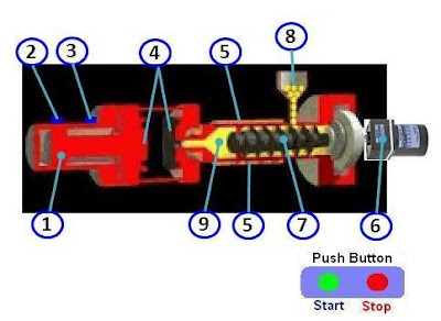

Information on Drawing Numbers :
1.Cylinder to Reverse - Forward for Molding Dies
2. Limit Switch Reverse for Molding Dies
3. Limit Switch Forward for Molding Dies
4. Molding Dies
5. Heater to Heat the Raw Materials
---(Heater is Controlled by Temperature Controller)
6. Speed Control Motor to Rotate the Screw
7. Screws to Inject material into the Molding Dies
8. Plastic Raw Material Seeds
9. Materials that are Liquid
Number Of Inputs and Output PLC applied :
1. Number Of Inputs PLC is 7 Input :
--- 1 Unit Input for Push Button Start.
--- 1 Unit Input for Push Button Stop.
--- 1 Unit Input for Temperature is Reached, the Signal from the Contact Contactor or Output the Temperature Controller.
--- 1 Unit Input for Alarm Heater, the Signal from the Heater Element Burnout Detector.
--- 1 Unit Input for Alarm Motor, the Signal from the Speed Control Motor.
--- 1 Unit Input for Limit Switch Reverse from Cylinder Molding.
--- 1 Unit Input for Limit Switch Forward from Cylinder Molding.
--- Total Number Of Inputs PLC is Minimum 7 Input Unit.
Remarks To Alarm Heater or Motor :
If ALARM or FAULT Then Output Alarm = OFF.
If NO ALARM Then Output Alarm = ON.
2. Number Of Output PLC is 4 Output :
--- 1 Unit Output for Speed Control Motor ( ON / OFF Motor for Screw ) .
--- 2 Unit Output for Solenoid to Pneumatic Cylinder Molding Reverse and Molding Forward.
--- 1 Unit Output for Heater ON / OFF to Temperature Controller.
--- Total Number Of Outputs PLC is Minimum 4 Output Unit.
Sequence PLC Programming for Injection Molding Machine :
Step 1 :
a. If Push Button Start = ON Then Heater = ON.
Please Click : Heater Controller with PLC
b. If Temperature is Reached And Alarm Heater = ON And Alarm Motor = ON ( See Remarks above) Then Injection Molding is Ready for use.
Step 2 :
a. If Push Button Start = ON And Injection Molding is Ready And Limit Switch Reverse from Cylinder Molding = ON Then Solenoid to Cylinder Molding Forward = ON.
b. If Solenoid to Cylinder Molding Forward = ON And Limit Switch Forward from Cylinder Molding = ON Then Motor for Screw = ON And Timer Motor ON Activated.
c. Data Set Value Timer Motor ON = 10 Second ( Data Setting = 10 second (Can be Changed) ) for Volume of Materials into Molding Dies.
d. If Timer Motor ON = ON Then Motor for Screw = OFF And Timer Wait Cool Activated (Wait for the Cool Material ) .
e. Data Set Value Timer Wait Cool = 15 Second ( Data Setting = 15 second (Can be Changed) ) for Wait for the Cool Material.
f. If Timer Motor Wait Cool = ON Then Solenoid to Cylinder Molding Reverse = ON.
g. If Solenoid to Cylinder Molding Reverse = ON And Limit Switch Reverse from Cylinder Molding = ON Then Solenoid to Cylinder Molding Forward = ON.
h. Continuous Process.
Download Simulation Process : PLC for Injection Molding Machine
Step 3 :
a. If Push Button Stop = ON Then Injection Molding Machine Stop ( All System OFF ).
Can You make Program Ladder PLC ?
If Can't :
PLC Omron Programming for Injection Molding Machine
PLC Mitsubishi Programming for Injection Molding Machine
PLC Keyence Programming for Injection Molding Machine