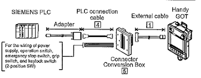
In this article will explain PLC connection diagram of a SIEMENS PLC – SIMATIC S7. When connecting the handy GOT to a Siemens PLC, a relay cable must be created or an external cable which is untied must be processed. Connect the cable connector for PLC communication in the environmental protection back cover to RS-232 connector. The system configuration as shown below:

The following provides the connection diagram of RS-232 cable connecting Handy GOT to PLC. When preparing the cable of RS-232 must be 6m or less.

Below are the steps of connecting to HMI Adapter:
1. Communication settings, it sets the communication settings of HMI adapter by operating the GOT.
2. Connecting to SIMATIC S7
• Set the communication setting of PLC and PC/PPI cable.
• Set the communication setting of PLC by operating the Siemens programming tools.
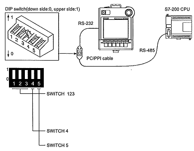
• PC/PPI cable setting, it sets the transmission speed by operating the DIP switch on the PC/PPI cable.

Precautions for connecting diagram of PLC Siemens Simatic S7 are error information can not be monitored when the GOT is connecting to PLC Siemens SIMATIC S7. When powering ON the system, turn ON all PLC CPUs before turning ON the GOT. If the GOT is turned ON before power up the PLC CPUs, restart the GOT. When powering OFF a PLC CPU at another station, monitoring by the GOT is stopped. To resume the monitoring, restart the GOT. Monitoring will not be resumed on GOT even if the PLC CPU is turned ON again.