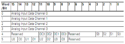
For each module, slot x, words 0 through 3 contain the analog values of the inputs. Word 4 and 5 provide sensor or channel status feedback. The input data file for each configuration is shown below.

The bits are defined as below:
• Sx = General status bits for inputs channel 0 through 3. This bit is set (1) when an error (over or under range, open circuit or input data not valid condition) exist for that channel, or there is a general module hardware error. An input data not valid condition is determined by the user program.
• OCx = Open circuit indication for channel 0 through 3, using either RTD or resistance inputs. Short circuit detection for RTD inputs only. Short circuit detection for resistance inputs is not indicated because 0 is valid number.
• Ox = Over-range flag bits for input channel 0 through 3, using either RTD or resistance inputs. These bits can be used in the control program for error detection.
• Ux = Under-range flag bits for channel 0 through 3, using RTD inputs only. These bits can be used in control program for error detection. Under-range detection for direct resistance inputs is not indicated because 0 is valid number.