1.Functions Used of Omron CP1L PLC
1.1.Pulse Output by Built-in Output
Pulse signal outputs from the built-in output of a CPU unit can be used for
positioning and speed control of a servo motor driver with up to 2 axes.
2.Operation Overview of Servo Positioning
The following example is for a single-axis handling machine that is used to transfer product.
Origin search will be executed, followed by positioning operations to points A and B.
3.Origin Search of Servo Positioning
An accurate origin search that makes use of various I/O signals (origin proximity input signal, origin input signal, positioning completed signal, error counter reset output, etc.) can be executed with a single instruction.
4.Servo Positioning
Common settings for the positioning operations are as follows:
• Target frequency 50kHz
• Acceleration/deceleration ratio 2000Hz/4ms
• Initial frequency 0Hz
(1) After completion of the origin search, the equipment will be positioned to point A (-1000) by absolute pulse specification (absolute coordinate system).
(2) After positioning to point A, the equipment will be positioned to point B (100000) by absolute pulse specification (absolute coordinate system).
(3) Positioning of points A and B are repeated. Because absolute pulse specification is used, the positioning SV for (3) will be the same as for (1).
5. Wiring Example of Servo Positioning
Note:
*Insert a resistance of 1.6 to 2.2k , so that the current is within the 7 to 15mA range.
*For a 20/30/40-point CPU, the origin proximity input (pulse 0) will be 0CH10bit.
6.PLC Setup of Servo Positioning
Specify the settings for pulse output 0.
1. Open the PLC Settings dialog box.
2. Click the Pulse Output 0 tab.
3. Set the following settings.
4. Close the PLC Settings dialog box.
5. To apply changes made to the PLC settings, turn the PLC power ON.
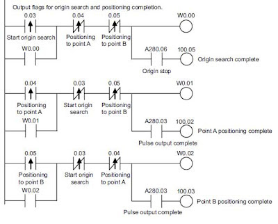
7. Servo Positioning Programming Example
7.1.Ladder Program
7.2.DM Area Setup Example
Source : www.omron.com


