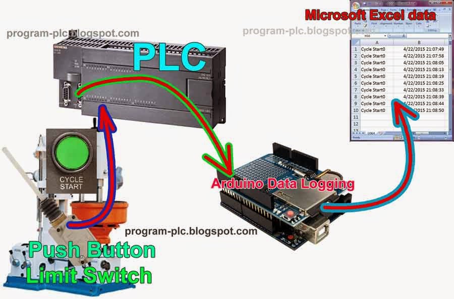
Data logging on PLC, this function is to record the date and time, then stored into the memory card / sd card, and then processed by data acquisition.
A data logging is a data acquisition, but the data acquisition is not always a data logging.
Example for this application: in general usually temperature recording, but other functions can be used to product reject recording, emergency stop recording, alarm recording, data logging for operators began to work, data logging for machine start operation and machine stop/finish operation, data logging for cycle start operation, and others.
This article about data logging for cycle start of machine operation
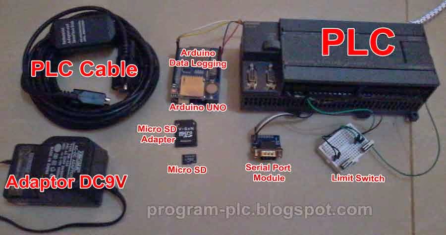
Hardware preparation:
1. Arduino Data Logging Shield
2. Arduino UNO
3. Serial Port Module: TTL to RS232 male
4. PLC Cable : RS232 PPI Multi Master Cable
5. Siemens S7-200 PLC
6. Adaptor DC9V
7. Micro SD Card and format to FAT16 or FAT32 (I use 4GB).
8. Micro SD Adapter
9. Push Button Switch or Omron Limit Switch WLNJ-2 or other.
Hardware Connections:
Download Project File for Data Logging on PLC:
1. Arduino Project file, click here
for folder SimpleModbusMaster and RTClib copy-paste into folder C:\Program Files (x86)\Arduino\libraries
2. PLC Ladder Programming project file, click here
Video Test:
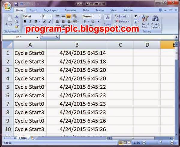
Data loggers recorded and Microsoft Excel:
Arduino Code for Data Logging on PLC:
#include <SimpleModbusMaster.h>
//Arduino Serial Port Connect to Port 0 of Siemens PLC S7 200
//for more info program-plc.blogspot.com
#define slaveAddr 1
#define baud 9600
#define timeout 1000
#define polling 200
#define retry_count 0
#define TxEnablePin 2
enum
{
  PACKET1,
  PACKET2,
  TOTAL_NO_OF_PACKETS
};
Packet packets[TOTAL_NO_OF_PACKETS];
packetPointer packet1 = &packets[PACKET1];
packetPointer packet2 = &packets[PACKET2];
unsigned int readRegs[1];
unsigned int writeRegs[2];

#include <SPI.h>
#include <SD.h>
#include <Wire.h>
#include "RTClib.h"

// change this to match your SD shield or module;
// Arduino Ethernet shield: pin 4
// Adafruit SD shields and modules: pin 10
// Sparkfun SD shield: pin 8
const int chipSelect = 10;
RTC_DS1307 RTC;
File LoggingFile;
DateTime dt;
boolean save=true;

void setup() {
  pinMode(10, OUTPUT);
  if (!SD.begin(chipSelect)) {
    ArduinoReset();
    return;
  }

  Wire.begin();
  RTC.begin();

  //Auto Setting
  //Resets the RTC chip with Remove the battery
  //from the holder while the Arduino is not powered
  //Wait 3 seconds and then reinsert the battery.
  //Remove SD Card and Upload Program
  //Insert SD Card
  if (!RTC.isrunning()) {
    // following line sets the RTC to the date & time this sketch was compiled
    RTC.adjust(DateTime(F(__DATE__), F(__TIME__)));
  }

   //Manual Setting
   // This line sets the RTC with an explicit date & time, for example to set
   // January 21, 2015 at 3am you would call:
   // RTC.adjust(DateTime(2015, 1, 21, 3, 0, 0));


  modbus_construct(packet1, slaveAddr, READ_HOLDING_REGISTERS, 0, 1, readRegs);
  modbus_construct(packet2, slaveAddr, PRESET_MULTIPLE_REGISTERS, 1, 2, writeRegs);
  modbus_configure(&Serial, baud, SERIAL_8E1, timeout, polling, retry_count, TxEnablePin, packets, TOTAL_NO_OF_PACKETS);

}

void loop() {
    String DataLogging=""; //buffer data for date time records
    dt = RTC.now();
    DataLogging += ",";
    DataLogging += String(dt.year(), DEC);
    DataLogging += String("/");
    DataLogging += String(dt.month(), DEC);
    DataLogging += String("/");
    DataLogging += String(dt.day(), DEC);
    DataLogging += String(" ");
    DataLogging += String(dt.hour(), DEC);
    DataLogging += String(":");
    DataLogging += String(dt.minute(), DEC);
    DataLogging += String(":");
    DataLogging += String(dt.second(), DEC);

    String FileName = "log"; //for filename + auto month
    FileName += String(dt.month(), DEC);
    FileName +=".csv";

    modbus_update();
    word check0 = (word)readRegs[0];
    writeRegs[1]= (word)(dt.minute()*100);
    writeRegs[1]+= (word)dt.second();
    if(check0==0){
      writeRegs[0]=0;
      save=true;
    }

    if(check0>0 && save){
      writeRegs[0]=0;
      char FileName1[FileName.length()+1];
      FileName.toCharArray(FileName1, sizeof(FileName1));
      LoggingFile = SD.open(FileName1, FILE_WRITE);
      if (LoggingFile) {
        //Write to SD
        for (int num = 0; num < 12; num++) {
         //Cycle Start0 to Cycle Start11
          if(bitRead(check0, num)==1)LoggingFile.println("Cycle Start"+String(num)+DataLogging);
        }
        LoggingFile.flush();
        LoggingFile.close();
        writeRegs[0]=(word)check0;
        save = false;
      }else {
        ArduinoReset();
      }
    }

}


void ArduinoReset()
{
asm volatile ("  jmp 0");
}
Labels:
Arduino
Arduino Data Logging Shield
Arduino Microcontroller
Data Logging
PLC and Arduino
PLC Application
PLC Data Logging
PLC Real Time Clock
Programmable Logic Controller
Arduino
Arduino Data Logging Shield
Arduino Microcontroller
Data Logging
PLC and Arduino
PLC Application
PLC Data Logging
PLC Real Time Clock
Programmable Logic Controller


