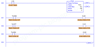
In programming PLC, sometime we need to evaluate input or do action after a period of times, or we need to turn ON/OFF a lamp in certain delay period. We can do this with timer functionality in PLC. Figure bellow shows the timer format used by Allen-Bradley. It consists of a timing block containing the timer number (address), timer base, preset, and accumulated times. Timer base can be set as 1 second or 0.01 second. The preset can be programmed with any value from 0 to 32,767. If one second base was assigned, the maximal value would equal 9.1 hours (32,767 ÷ 3600 = 9.1). If a time based of 0.01 s was assigned, then the maximal timing value approximately 5.5 minutes (32,767 × 0.01 ÷ 60 = 5.46).
There are the enable (EN) bit and done (DN) bit that indicate the status of the timer. EN bit is set to 1 (or is true) to activate the timer block. DN bit is set to 1 (true) when the accumulated value equals the preset value and the timer has timed out. The timer address (T4:0) means the PLC uses timer file 4, timer 0. It identified 4 as timer file number and 0 as timer number. File 4 is the default file from data table for timer used by PLC-5, SLC 500, and MicroLogix family. PLC-5 can be programmed to use files 3-999 for additional timer files, SLC 500 can be programmed to use 9-255, and MicroLogix 1000 is only able to use file 4.
In this tutorial you have to fill this requirement before continue to the next step:
Hint: you can select TON timer block from Timer/Counter toolbar.
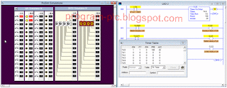
Download the program to PLC simulator, then run it. You can analyze Timer Table data by right click timer block program and select Goto Data Table. Don’t forget to turn switch I:1/0 to start timer.
From above result, it is clear that TON instruction can be used to turn ON or OFF after a preset time interval. The timer begin timing when the rung is true. TT bit indicates that the timer is counting. TT bit will become false after Accumulator equals Preset value and the DN (done) bit also set as true at that time.
YouTube Programming Timer ON Delay of Allen Bradley RSLogix-500 PLC Simulator
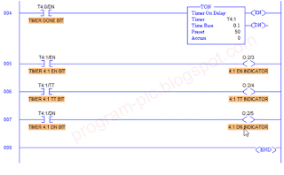
Timer T4:1 will be executed after T4:0 finish the calculation. This technique will be useful when single maximal timer calculation insufficient with specification we needed. The total preset from in this cascade timer is 150 (100 + 50). It is the total amount of Preset from timer T4:0 and T4:1.
The timer should operate in continuous loop with timer 1 starting timer 2. When timer 2 is done, it reset timer 1 with its DN bit. When timer 1 reset, it turn timer 2 reset also because timer 1 done bit become low (T4:1/DN = 0). The sequence is back to original and start once again.
Hint: select TOF block timer from Timer/Counter toolbar.
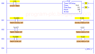
TOF (Timer Off Delay) works as the opposite of TON (Timer On Delay). TOF began to calculate timer after it has low signal to the timer block (I:1/0 = false). The timing bit (TT) and accumulator start counting when EN bit became low (false). After the Accumulator reached the preset value, it will set DN bit to low and the indicator (O:2/2) become turn off. Here a figure that show the difference bit value of timer in its life cycle.
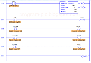
RTO timer function is as same as TON timer but when it begun timing, it hold the Accumulator value if the rung become false or the power is lost. When the rung goes true again, then the timer begins timing from the last accumulated time. RTO measure the cumulative period during the rung condition is true. The following figure show the value of RTO timer when switch 0 goes false or change to PGM mode. To reset the Accumulator value you have to turn switch 1 to ON then OFF again. You can change switch 1 as normally open switch to reset Accumulator easily.
There are the enable (EN) bit and done (DN) bit that indicate the status of the timer. EN bit is set to 1 (or is true) to activate the timer block. DN bit is set to 1 (true) when the accumulated value equals the preset value and the timer has timed out. The timer address (T4:0) means the PLC uses timer file 4, timer 0. It identified 4 as timer file number and 0 as timer number. File 4 is the default file from data table for timer used by PLC-5, SLC 500, and MicroLogix family. PLC-5 can be programmed to use files 3-999 for additional timer files, SLC 500 can be programmed to use 9-255, and MicroLogix 1000 is only able to use file 4.
In this tutorial you have to fill this requirement before continue to the next step:
- PLC basic programming : Logixpro PLC Simulator
- Software LogixPro500
Step 1:TON Timer (Timer ON Delay)
Open LogixPro Simulator, then select menu Simulations >> I/O Simulator. Clear any existing program by select File >> New, then enter the program bellow. Make sure you set any value as seen in figure.Hint: you can select TON timer block from Timer/Counter toolbar.
Download the program to PLC simulator, then run it. You can analyze Timer Table data by right click timer block program and select Goto Data Table. Don’t forget to turn switch I:1/0 to start timer.
From above result, it is clear that TON instruction can be used to turn ON or OFF after a preset time interval. The timer begin timing when the rung is true. TT bit indicates that the timer is counting. TT bit will become false after Accumulator equals Preset value and the DN (done) bit also set as true at that time.
YouTube Programming Timer ON Delay of Allen Bradley RSLogix-500 PLC Simulator
Step 2: Cascade TON Timer
Add program in the following figure after program in step 1. Then guest what will be happen to the timer T4:1?Timer T4:1 will be executed after T4:0 finish the calculation. This technique will be useful when single maximal timer calculation insufficient with specification we needed. The total preset from in this cascade timer is 150 (100 + 50). It is the total amount of Preset from timer T4:0 and T4:1.
Step 3: Self Resetting Timer
Stop your running program by place the PLC into PGM mode. Modify our cascade timer in step 2, add Examine if Open (XIO) and set it as T4:1/DN. Download the program and run the simulation.The timer should operate in continuous loop with timer 1 starting timer 2. When timer 2 is done, it reset timer 1 with its DN bit. When timer 1 reset, it turn timer 2 reset also because timer 1 done bit become low (T4:1/DN = 0). The sequence is back to original and start once again.
Step 4: TOF Timer (Timer OFF Delay)
Create new program of modify your last program as seen as the following figure. Make sure you use TOF block timer. After your program finish, download it to PLC simulator. Then make sure switch I:1/0 is closed before you enter run mode. Now let see what happen in simulation!Hint: select TOF block timer from Timer/Counter toolbar.
TOF (Timer Off Delay) works as the opposite of TON (Timer On Delay). TOF began to calculate timer after it has low signal to the timer block (I:1/0 = false). The timing bit (TT) and accumulator start counting when EN bit became low (false). After the Accumulator reached the preset value, it will set DN bit to low and the indicator (O:2/2) become turn off. Here a figure that show the difference bit value of timer in its life cycle.
Step 5: RTO Timer (Retentive Timer ON)
Modify or create new program as the following figure. This time we use RTO timer block. Put toggle switch at rung 001 and place RES block from Timer/Counter toolbar. After that download your program to PLC and enter run mode. Make sure switch 0 (I:1/0) and switch 1 (I:1/1) are in open condition.RTO timer function is as same as TON timer but when it begun timing, it hold the Accumulator value if the rung become false or the power is lost. When the rung goes true again, then the timer begins timing from the last accumulated time. RTO measure the cumulative period during the rung condition is true. The following figure show the value of RTO timer when switch 0 goes false or change to PGM mode. To reset the Accumulator value you have to turn switch 1 to ON then OFF again. You can change switch 1 as normally open switch to reset Accumulator easily.
Labels:
PLC Simulator
PLC Simulator

