GE Fanuc PLC Programming Software


In this article will explain about SoftPLC programming PLC that using GE Fanuc 90/30 I/O driver. It allows to access up to eight PCIF host I/O interface adapters. The driver consist 3 files, namely GE90/30.TLM, GECONFIG.EXE, and GE.LST. GE90/30.TLM is the runtime component, GECONFIG.EXE is a utility of displaying I/O information and generating an I/O report and GE.LST is the master configuration files.

When you install the SoftPLC you need to install GE90/30.TLM, GECONFIG.EXE and GE.LST under the \SPLCZ\IODVR\ directory. GE90/30.TLM is made known to SoftPLC by a line entry in the MODULE.LST file. Each I/O driver entry in MODULE.LST has to start with keyword “DRIVER”. Put the following line in the MODULE.LST file to be able to interface GE 90/30 I/O with SoftPLC:

DRIVER=C: \SPLCZ\IODVR\GE9030.TLM CFGFILE=C: \SPLCZ\IODVR\GE.LST

Here is the step by step to setting up the driver:
1. Edit the ‘Port’ column under the [CARDS] section of the GE.LST file for each of the card you will use. This normally resides in \SPLCZ\IODVR.
2. Set the switch settings on each card and install them in the host computer.
3. Attach the I/O racks, using a terminating resistor pack as might be needed on the last rack in each chain.
4. Insert the I/O modules and power up the racks.
5. Run the GECONFIG.EXE program from the \SPLCZ\IODVR directory and give it the name of your CFGFILE, which is normally GE.LST: C:>GEFONFIG GE>LST.
6. Press F3 to display all the communicating I/O module for each I/O network.
7. Press F4 to generate the GECARD.REP text file, which is a complete definition of how SoftPLC data table memory will be consumed for each I/O network.
8. Press F5 to generate default configuration file specification for each smart module.
9. Press F10 to exit GECONFIG.EXE.
10. Look at GECARD.REP and take note on how much data table memory you will need to allocate for each driver data type, for each I/O network.
11. Make the final edits to GE.LST, paying attention to the 5 xxWords columns for each I/O network.

Push ON Push OFF With Data Memory PLC Omron


PLC Type Series-CV Omron , Name Input / Output PLC :

INPUT PLC :
0000.00 ; Push Button Switch ( without lock ).

OUTPUT PLC :
0005.00 ; Lamp.


PLC programming for Push ON Push OFF With Data Memory PLC Omron :
Push ON Push OFF


Reading Ladder PLC Programming for Push ON Push OFF with Data Memory PLC Omron :

Step 1 :
Push ON , Lamp ON
a.If 0000.00 = ON Then Increment D00000 ( INC with Differentiate Up ) And D00000 = 1.
b.If D00000 = 1 Then 0005.00 = ON.
c.If 0000.00 = OFF Then D00000 = 1 And 0005.00 = ON .

Step 2 :
Push ON, Lamp OFF
a.If 0000.00 = ON Then Increment D00000 (Differentiate Up) And D00000 = 2.
b.If D00000 = 2 ( EQU ) Then D00000 = 0 ( MOV ).
c.If D00000 = 0 Then 0005.00 = OFF.
d.If 0000.00 = OFF Then D00000 = 0 And 0005.00 = OFF .

Please Download Programming for SYSWIN :
Push ON Push OFF With Data Memory PLC Omron

See : Push ON Push OFF

MOV instruction on Omron PLC


MOV(030) - Move
MOV instructions
Purpose:
Copies the contents of S to D.
Copies S to D
Operand Data Areas:
S: Source word CIO, G, A, T, C, #, DR, IR
D: Destination word CIO, G, A, T, C, DR, IR

Examples of the use of MOV instruction :
MOV
1. If 0000.00=ON Then Value in D00000=2
2. If 0000.00=OFF Then Value in D00000=2
3. If 0000.01=ON Then Value in D00000=0
4. If 0000.01=OFF Then Value in D00000=0

INC instruction on Omron plc


INC(090) - Increment BCD
INC instructions
Purpose:
Increments Wd by the operand by 1, without affecting Carry (CY).
Further information can be found in BCD calculations.

Operand Data Areas:
Wd: Increment word CIO, G, A, DM, DR, IR

Examples of the use of INC instruction :
INC
If 0000.00=ON Then Increments D00000 by the operand by 1


Differentiate Up INC
with Differentiate Up
If 0000.00=ON Then D00000=1
If 0000.00=OFF Then D00000=1
If 0000.00=ON Then D00000=2
If 0000.00=OFF Then D00000=2, etc.

EQU instructions on Omron PLC


EQU(025) - Equal
EQU instructions
Purpose:
Compares the content of Cp1 to the content of Cp2. Creates an ON execution condition if the two values are equal or an OFF condition if they are not equal.

Operand Data Areas:
Cp1: 1st compare word CIO, G, A, T, C, DM, #, DR, IR
Cp2: 2nd compare word CIO, G, A, T, C, DM, #, DR, IR

Examples of the use of EQU instruction :
EQU
If D00000=2 Then 0005.00=ON


Differentiate Up EQU
with Differentiate Up
If D00000=2 Then 0005.01= Diff. Up ON

PLC Programming with RSLogix 5000


In this article will show you how to program RSLogix 5000 controllers with the relay ladder programming language.
1. To program the ladder diagram you need to organize ladder diagram as rungs on a ladder and put instructions on each rung. There are 2 types of basic instructions:
• Input instruction: An instruction that checks, compares, or examines specific conditions in your machine or process.
• Output instruction: An instruction that takes some actions, such as turn on the devices, turns off the devices, copy data or calculate a value.
program ladder diagram

2. The next process is to write the ladder logic. Separate the conditions to check from the action to take. Choose the appropriate input instruction for each condition and the appropriate for the output instruction for each action. Below are 2 simple instructions to learn how to write ladder diagram logic.
write ladder diagram logic

3. Determine how to arrange the input instructions on the rung:
input instructions

4. Place at least one output instruction to the right of input instruction.
output input instruction

5. Choose a tag name for operand.
tag name for operand

6. Choose a name or an existing tag.
• Double click operand area --> LD A text entry box opens.
• Select the name.
Select the name
• Press [Enter] or click a different spot on the diagram.

7. Drag a tag from the Tags Window.

8. Assign an immediate (constant) value.
• Click the operand area of the instruction.
operand area
• Type the value and press [enter].

9. Verify the routine.
• In the top-most toolbar of the RSLogix 5000 window, click Verify .
• If any errors are listed at the bottom of window:
a. To go to the first error or warning, press [F4].
b. Correct the error according to the description in the result window.
c. Go to step a.
• To close the result window, press [Alt] + [1].

Allen Bradley PLC Basics


Allen Bradley PLC is a product of a fairly widely used throughout the world. Allen Bradley always marked by success stories and reliability. Therefore, many companies are very fanatic with Allen Bradley products.

Generally, Allen Bradley PLC programmed using ladder logic using the software programming, i.e. RS-Logic. But this time when technology increasingly prevalent Hybrid, Allen Bradley PLC also has the ability to produce a hybrid that resembles the DCS, PLC is now marketed under the name of the Control Logix.

In order to have high capability for process control applications, Control Logix equipped with the function block and clocking capabilities up to 32 time frames. Allen Bradley PLC already has ranging generations from PLC 3, PLC-5, SLC and the last is the Control Logix.

Control Logix is the latest version of Allen Bradley PLC. This PLC was created to for deeper market penetration that had been controlled by the DCS, namely for Process Control applications.

Basic Control Logix technology is using hybrid technology. With this capability, the Control Logix can be entered in the application that requires PLC and DCS applications need.

Another feature of the Control Logix who have not owned by the previous generation such as the SLC 500 is the ability of redundancy, both power and logix (CPU).

Programming PLC Watchdog Timer


A Watchdog Timer is a timer that is used to make sure some unexpected problem does not keep the system processing as it should. There are several of them in the SLC and they are common to every PLC. In the most common sense (and probably what you are referring to), there is a Watchdog Timer that covers the processor scan. If the scan takes too long to complete due to a poorly written loop or jump routine, the Watchdog Timer will expire and fault out the PLC. This is a major fault and is only recoverable by clearing the fault, fixing the problem, and starting the PLC back up.

It is primary purpose is to prevent the PLC from going into LaLa land (technical term) due to a programming error. You generally will not have a problem with this error. You can change the watchdog timer period in the case that you have a massive program that needs a long time to process. Generally that means you have the wrong processor for the job - need more power. With the SLC there are also hardware watchdogs that look for unexpected hardware issues, STI watchdog, and the program scan watchdog.

The Watchdog Timer was conceived shortly after Digital computer began to be used in control application. According to System Level Integrity there are three basics types of Watchdog Timers which are used in control system supervision:
• Basic CPU Watchdog
• Control system Watchdog
• Communications Watchdog

The most basic is the Watchdog Timer local to the CPU board. This device or circuit monitors CPU activity local to the microprocessor and if it fails to detect CPU activity, it resets the microprocessor. In most control system applications, it is required to supervise the system’s ability to stay in control of a machine or process.

PLC Programming Standards


A standard programming interface allows people with different backgrounds and skills to create different elements of a program during different stages of the software lifecycle such as, specification, design, implementation, testing, installation and maintenance. According to the PLC Open organization, standardizing the programming interface harmonizes the way people design and operate industrial control.

The primary standard available for programmable logic controller (PLC) programming is defined in IEC 61131. This standard has been embraced by many other international standards organizations. For example, the American National Electrical Manufacturers Association (NEMA) standard IA 2.3-2005 is based on IEC 61131-3 as is the British Standard BS EN 61131-3.

IEC 61131, this standard is broken down into:
• IE 61131-1 Programmable controllers – Part 1: General information.
• IEC 61131-2:2003 Programmable controllers – Part 2: Equipment requirements and tests.
• IEC 61131-3:2003 Programmable controllers - Part 3: Programming languages.
• IEC 61131-4:2004 Programmable controllers – Part 4: User guidelines.
• IEC 61131-5:2000 Programmable controllers – Part 5: Communications.
• IEC 61131-7: Programmable controllers – Part 7: Fuzzy control programming.
• IEC 61131-8:2003 Programmable controllers – Part 8: Guidelines for the application and implementation of programming languages.

The main sections of interest from a PLC programming standards standpoint are IEC 61131-3; 61131-4 and 61131-8.

IEC 61131-3 specifies syntax and semantics of programming languages for programmable controllers, 61131-4 is general in nature but does address some safety related matters, while 61131-8 applies to the programming of programmable controller systems using the programming languages defined in IEC 61131-3. It also provides guidelines for the implementation of these languages in programmable controller systems and their programming support environments (PSEs).

Push ON Push OFF With Counter PLC Keyence


PLC Type KV Keyence , Name Input / Output PLC :

INPUT PLC :
0000 ; Push Button Switch ( without lock ).

OUTPUT PLC :
0500 ; Lamp.


PLC programming for Push ON Push OFF With Counter PLC Keyence :
Push ON Push OFF


Reading Ladder PLC Programming for Push ON Push OFF with Counter PLC Keyence :

Step 1 :
Push ON , Lamp ON
a.If 0000 = ON Then Present Value ( C000 = 1 And C001 = 1 ) And ( C000 = ON And C001 = OFF ).
b.If 0000 = OFF Then C000 = ON And C001 = OFF.
c.If C000 = ON Then 0500 = ON.

Step 2 :
Push ON, Lamp OFF
a.If 0000 = ON Then C001 = ON And Present Value ( C000 = 0 And C001 = 0 ) And ( C000 = OFF And C001 = OFF ).
b.If 0000 = OFF Then C000 = OFF And C001 = OFF.
c.If C000 = OFF Then 0500 = OFF.

Please Download Programming for KV Builder :
Push ON Push OFF With Counter PLC Keyence

See : Push ON Push OFF

Modicon PLC Programming


Modicon can mean Modicon PLC, the first programmable logic controller or PLC. The brand has gone through several owners and is now owned by Schneider Electric. Then now Modicon (Schneider Electric) was designed MODBUS as a commonly used industrial communications protocol. It allows the exchange of data between PLCs and computers. But it has become widely used by many PLC manufacturers and industrial networks.

MODBUS is a common means of gathering data from many different sources for viewing operations, archiving and troubleshooting from a central remote location. It is widely used and a fairly simple protocol. Depending on the application a newer protocol may have more advantage.

Typically a PC is set up running such programs as Wonderware, Intellution or LabVIEW in one location to gather data from various processes around the factory. Another application is for setting up remote factory process controllers (such as other PLCs like Allen-Bradley, Siemens, PLCDirect, etc.) to respond to different levels or modes that are being transmitted from the device.

Modbus protocol establishes the format for the master's query by placing into it the device (or broadcast) address, a function code defining the requested action, any data to be sent, and an error-checking field. The slave's response message is also constructed using Modbus protocol. It contains fields confirming the action taken, any data to be returned, and an error-checking field. If an error occurred in receipt of the message, or if the slave is unable to perform the requested action, the slave will construct an error message and send it as its response.

PLC Operator Interface


PLC operator interface can be communicated to higher level decision components of an enterprise to facilitate automated control and dynamics of the enterprise. Operator interface components are provided that automatically adapt interface control functionality based on the transaction events.

In industrial automation field, the function of operator interface is very important to control and monitor loops, combustion controls and conveyors. Now PLC operator interface technologies more and more advance.

The examples of operator interface technologies from some OEMs are:

Prizm, they have produced the next generation of PLC operator interface in with touch screen facility. Equipped with support for demanding visualization tasks, it allows easy operations and monitoring of the complete process on your control desk. Critical process parameters, plant operations, machine status can be monitored easily.

HIO, operator interface with I/O. It is not just operator interface but also have analog and digital I/O on the back. PID and configurable high-speed counter functionality is also included.

Xycom Pro-face, operator interface touch screens have one of largest selection of HMI serial and Ethernet protocols. It is also available in various industrial network interfaces.

Advantech WebOIT touch screens are a Windows CE computer that will publish real-time dynamic and animated graphic screens to standard browsers. The software includes math functions, report generation, archiving, alarms, batch recipes, and interface for PLCs.

PLC Connection Diagram


In this article will explain PLC connection diagram of a SIEMENS PLC – SIMATIC S7. When connecting the handy GOT to a Siemens PLC, a relay cable must be created or an external cable which is untied must be processed. Connect the cable connector for PLC communication in the environmental protection back cover to RS-232 connector. The system configuration as shown below:
system configuration

The following provides the connection diagram of RS-232 cable connecting Handy GOT to PLC. When preparing the cable of RS-232 must be 6m or less.
connection diagram

Below are the steps of connecting to HMI Adapter:
1. Communication settings, it sets the communication settings of HMI adapter by operating the GOT.

2. Connecting to SIMATIC S7
• Set the communication setting of PLC and PC/PPI cable.
• Set the communication setting of PLC by operating the Siemens programming tools.
• PC/PPI cable setting, it sets the transmission speed by operating the DIP switch on the PC/PPI cable.
connecting to HMI Adapter

Precautions for connecting diagram of PLC Siemens Simatic S7 are error information can not be monitored when the GOT is connecting to PLC Siemens SIMATIC S7. When powering ON the system, turn ON all PLC CPUs before turning ON the GOT. If the GOT is turned ON before power up the PLC CPUs, restart the GOT. When powering OFF a PLC CPU at another station, monitoring by the GOT is stopped. To resume the monitoring, restart the GOT. Monitoring will not be resumed on GOT even if the PLC CPU is turned ON again.

Fuzzy Logic Controller in PLC


Fuzzy logic is the system that can not be modeled with linear differential equations. Rules and memberships sets are used to make a decision. This rules concern how fast to fill a bucket, based upon how full it is. A simple verbal rule se as following:
• If (bucket is full) then (stop filling)
• If (bucket is half full) then (fill slowly)
• If (bucket is empty) then (fill quickly)

From the figure above there is question “what does it mean when the bucket is empty, half full or full?” We can define sets that indicate when something is true (1), false (0) or a bit of both (1-0). Refer to picture below:
linear differential equations
Consider the bucket is full set. When the height is 0, the set membership is 0. Nobody will think the bucket is full. As the height increase more people think the bucket is full until they all think the bucket is full. Notice that the angle function relates the valve angle to the fill rate. The sets are shifted to the right.

An example of a fuzzy logic controller is for controlling a servomotor as shown on picture below. This controller rules examine the system errors and the rate of error change to select a motor voltage. In this example the set memberships are defined with straight line.
example fuzzy logic controller
fuzzy logic controller

Fanuc PLC Programming


GE Fanuc is one of the United Stated companies which produce several programming language for PLC programming. One of the PLC Programming Software from Fanuc is Logicmaster 90. Logicmaster 90 software is the LD and SFC programming for series 90s PLC. It supports PLC configuration in an offline mode or online with the PLC.

Logicmaster 90 provides PLC configuration and PLC programming in a single package. Some function may be unique to certain models of the series 90s and may not support by others.

Logicmaster 90 software requires at a minimum a 386 PC with 4 Mb RAM and DOS 5.0. Logicmaster90’s power and versatility is the association of mnemonics with programming functions. Mnemonic allows the programmer to memorize the frequently used functions and quickly bypass superfluous keystrokes. Mnemonic helps speed up program editing, reducing overall development costs.

Logicmaster 90’s can give PLC identification configuration at each CPU. It allows user to assign a meaningful name to a system instead of just a number. You can also display the current memory allocated to both discrete references and register references.

Logicmaster90’s I/O configuration software defines the modules that are present in the PLC, assigns logical addresses to the modules and selects option for individual module. These logical addresses are independent of physical location or function.

Push ON Push OFF With Counter PLC Mitsubishi


PLC Type FX-Mitsubishi , Name Input / Output PLC :

INPUT PLC :
X000 ; Push Button Switch ( without lock ).

OUTPUT PLC :
Y000 ; Lamp.


PLC programming for Push ON Push OFF With Counter PLC Mitsubishi :
Push ON Push OFF


Reading Ladder PLC Programming for Push ON Push OFF with Counter PLC Mitsubishi :

Step 1 :
Push ON , Lamp ON
a.If X000 = ON Then Present Value ( C0 = 1 And C1 = 1 ) And ( C0 = ON And C1 = OFF ).
b.If X000 = OFF Then C0 = ON And C1 = OFF.
c.If C0 = ON Then Y000 = ON.

Step 2 :
Push ON, Lamp OFF
a.If X000 = ON Then C1 = ON And Present Value ( C0 = 0 And C1 = 0 ) And ( C0 = OFF And C1 = OFF ).
b.If X000 = OFF Then C0 = OFF And C1 = OFF.
c.If C0 = OFF Then Y000 = OFF.

Please Download Programming for GX Developer :
Push ON Push OFF With Counter PLC Mitsubishi

See : Push ON Push OFF

Function Block Diagram PLC


Function Block Diagrams (FBD) is a graphical language that allows the user to program elements in "blocks". The blocks can then be wired together like electrical circuits. FBD is one of the languages supported by IEC 1131.

A function block diagram is a diagram which describes a function between input variables and output variables. A function is described as a set of elementary blocks. Input and output variables are connected to blocks by connection lines. Inputs and outputs of the blocks are wired together with connection lines, or links. Single lines may be used to connect two logical points of the diagram:

• An input variable and an input of a block.
• An output of a block and an input of another block.
• An output of a block and an output variable.
Function Block Diagrams FBD
The connection is oriented, meaning that the line carries associated data from the left end to the right end. The left and right ends of the connection line must be of the same type. Multiple right connection is also called divergence can be used to broadcast information from its left end to each of its right ends. All ends of the connection must be of the same type.

The FBD supports:
• All IEC 61131-3 operators
• Multiple inputs / multiple outputs
• Negations
• Comments
• Set / Reset of outputs
• Jumps
• Bitmap graphics in library functions, function blocks and programs

PLC Flash Memory


Memory is where temporary data storage and a place to store the program to be started, where the program is the result of translation of the ladder diagram created by the user. Memory system on the PLC led to flash memory technology. By using flash memory it will be very easy for users to do programming or reprogramming repeatedly. In addition to the flash memory also has EEPROM which can be removed repeatedly.

Memory system is divided into blocks where each block has its own function. Some parts of the memory used to store the status of input and output, while the other parts of the memory used to store variables that are used in programs such as the timer and counter values.

Flash memory is a non-volatile computer storage that can be electrically erased and reprogrammed. It is a technology that is primarily used in memory cards and USB flash drives for general storage and transfer of data between computers and other digital products. It is a specific type of EEPROM (Electrically Erasable Programmable Read-Only Memory) that is erased and programmed in large blocks; in early flash the entire chip had to be erased at once.

Since flash memory is non-volatile, no power is needed to maintain the information stored in the chip. In addition, flash memory offers fast read access times (although not as fast as volatile DRAM memory used for main memory in PCs) and better kinetic shock resistance than hard disks. These characteristics explain the popularity of flash memory in portable devices.

Difference between PLC and Microcontroller


PLC is a special microcontroller designed for industrial application. It is for controlling machinery or processes. A microcontroller is a microprocessor that can be used for any type of application. The basic difference between PLC and microcontrollers is only the way of programming. Most common way of PLC programming is with graphical language Ladder logic programming which looks a little more similar to electrical schematics than a computer programming language.

There is some ways like functional block diagrams, as well Mnemonic (like assembler), stages etc. Second significant characteristic is the infinite loop (cycling) through the ladder start-to-end and again from start. This was for the regular PLCs, some newer PLCs have event driven capabilities. Also PLCs are more restricted in calculations.

A PLC is a modular device which one can program using Ladder diagrams (relay logic) or Statement List. It is optimized to handle several digital inputs and outputs, and is more rugged for use in industrial applications. Basically it scans the inputs, and determines the outputs based on the logical conditions programmed into it by the user. It internally uses a microcontroller to handle all input, output and logic scans. Application area is mostly industrial automation.

Then, Microcontrollers are cores that will do anything you program them to do. They probably can be used in each of the above applications, but with varying effectiveness. As always, your work is in discerning which option will work best in a given situation.

PLC with Touch Screen


Nowadays forms of PLCs more and more advanced by producing touch screen PLC. With the touch screen PLC, the users enable to operate it easier. One of PLC touch screen product is from HIO.
PLC touch screen HIO
This HIO product is Touch Screen HMI with PLC. HIO controllers can be used in application across many industries. Feature of HMI Touch screen is as follows:
• All features of Prizm Touch Screen Operator Interfaces.
• Integral digital inputs and outputs with optional analog I/O.
• Inputs connectable to PLC or for used internal program.
• Support for Ladder Logic and Analog control.
• High speed counters and timers.
• Universal serial ports to connect PLC or programming port.
• Etc.

Touch key in HIO units can be assigned tasks for three instances: when the key is pressed, while the key is pressed and when the key is released. Multiple tasks can be assigned to a key. In addition to above, tasks for data entry, alarm management, etc can be defined. These definitions allow complete flexibility in cursor control and key operations when changing data.

Screen tasks can be assigned before showing a screen, while showing a screen and after hiding a screen. Various types of object, data display, data entry objects and alarm objects can be defined. Data entry objects can have limits and math associated.

Push ON Push OFF With Counter PLC Omron


PLC Type Series-CV Omron , Name Input / Output PLC :

INPUT PLC :
0000.00 ; Push Button Switch ( without lock ).

OUTPUT PLC :
0005.00 ; Lamp.


PLC programming for Push ON Push OFF With Counter PLC Omron :
Push ON Push OFF


Reading Ladder PLC Programming for Push ON Push OFF with Counter PLC Omron :

Step 1 :
Push ON , Lamp ON
a.If 0000.00 = ON Then Present Value ( CNT000 = 1 And CNT001 = 1 ) And ( C000 = ON And C001 = OFF ).
b.If 0000.00 = OFF Then C000 = ON And C001 = OFF.
c.If C000 = ON Then 0005.00 = ON.

Step 2 :
Push ON, Lamp OFF
a.If 0000.00 = ON Then C001 = ON And Present Value ( CNT000 = 0 And CNT001 = 0 ) And ( C000 = OFF And C001 = OFF ).
b.If 0000.00 = OFF Then C000 = OFF And C001 = OFF.
c.If C000 = OFF Then 0005.00 = OFF.

Please Download Programming for SYSWIN :
Push ON Push OFF With Counter PLC Omron

See : Push ON Push OFF

PLC Inputs and Outputs


This article will discuss about Analog inputs and outputs with PLC-5. The PLC-5 logic ladder will be shown on figure at below. It will control an analog input card. The Block Transfer Write (BTW) will end configuration data from integer memory to analog card in rack 0, slot 0. The data from N7:30 to N7:66 describe the configuration for different input channels. Once the analog input card receives this it will start doing analog conversions.
This instruction is edge triggered, so it is run with the first scan, but the input is turned off while it is active, BT10:0/EN. This instruction will require multiple scans before all of the data has been written to the card.
instruction written to the card
The Block Transfer Read (BTR) will retrieve data from the card and store it in memory N7:10 to N7:29. This data will contain analog input values.
The PLC-5 ladder logic at figure below can be used to set analog output voltages with 1771-OFE Analog Output Card. The BTW instruction will write configuration memory to the card. Values also can be read back from the card using a BTR, but it is only valuable when checking the status of the card and detecting errors. The BTW is edge triggered so the BT10:0/EN input prevent the BTW from restarting the instruction until the previous block has been sent. The MOV instruction will change the output value channel 1 on the card.
instruction output value

PLC Analog Output


Analog outputs PLC much simpler than analog inputs PLC. To set an analog output an integer is converted to a voltage. This process is very fast, and does not experience the timing problems with analog inputs. But, analog outputs subject to quantization errors.
Figure below gives a summary of the important relationship. This relationship is almost identical to those of the A/D converter.
AD converter
Assume we are using an 8 bit D/A converter that outputs values between 0V to 10V. We have a resolution of 256, where 0 results in an output of 0V and 255 results in 10V. The quantization error will be 20mV. If we want output of a 6.234V, we would specify an output integer of 159, these would result in an output voltage of 6.235V. The quantization error would be 6.235V – 6.234V = 0.001V. You can see the calculation as below:
DA converter
The current output from a D/A converter is normally limited to a small value, typically less than 20mA. This is enough for instrumentation, but for high current loads such as motors, a current amplifier is needed. If the current limit is exceeded for 5V output, the voltage will decrease. If the current limit is exceeded for long periods of time the D/A outputs may be damaged.

Analog Input PLC


To input an analog voltage into PLC the continuous voltage value must be sample and then converted to a numerical value by an Analog to Digital Converter (ADC). Figure below shows continuous voltage change overtime. There are three samples on the figure.
analog voltage into PLC
The process of sampling data is not instantaneous, so each sample has a start and stop time. The time required to acquire the sample is called sampling time. A/D converter can only acquire a limited number of samples per second. The time between samples is called the sampling period T, and the inverse of sampling period is the sampling frequency or sampling rate. The sampling time is often much smaller than sampling period. The sampling frequency is specified when buying hardware, but for a PLC maximum sampling rate might be 20 Hz.

The data value sampled will be somewhere between the voltage at the start and end of the sample. The maximum (Vmax) and minimum (Vmin) voltages are a function of the control hardware. These are often specified when purchasing hardware, but usually are:
• 0V to 5V
• 0V to 10V
• -5V to 5V
• -10V to 10V

The number of bits of the A/D Converter is the number of bits in the result word. If the A/D Converter is 8 bits the result can read up to 256 different voltage levels. Most of A/D Converters have 12 bit, 16 bit converters are used for precision measurement.

Push ON Push OFF With PLC


Simulation Push ON Push OFF

Push ON Push OFF


Detail Push ON Push OFF With PLC:

Push ON Push OFF
Information on Drawing Numbers for Push ON Push OFF With PLC :
1. Push Button Switch ( without lock )
2. External Output, example Lamp
3. PLC or Programmable Logic Controller


Number Of Inputs and Output PLC applied :
1. Number Of Inputs PLC is 1 Input :
--- 1 Unit Input for Push Button Switch ( without lock ).
--- Total Number Of Inputs PLC is Minimum 1 Input Unit.


2. Number Of Output PLC is 1 Output :
--- 1 Unit Output for Lamp.
--- Total Number Of Outputs PLC is Minimum 1 Output Unit.


Sequence PLC Programming for Push ON Push OFF :

Step 1 : First Push
a. If Push Button Switch = ON Then Lamp = ON.
b. If Push Button Switch = OFF Then Lamp = ON.


Step 2 : Second Push
a. IF Push Button Switch = ON then Lamp = OFF.
b. IF Push Button Switch = OFF then Lamp = OFF.

Download Simulation Push ON Push OFF :
Please Click : Push ON Push OFF


Can You make Program Ladder PLC ?

If Can't :

Coming Soon

1. Methods : Internal Relay PLC

Push ON Push OFF With Internal Relay PLC Omron

Push ON Push OFF With Internal Relay PLC Mitsubishi

Push ON Push OFF With Internal Relay PLC Keyence


2. Methods : Counter PLC

Push ON Push OFF With Counter PLC Omron

Push ON Push OFF With Counter PLC Mitsubishi

Push ON Push OFF With Counter PLC Keyence


3. Methods : Data Memory PLC

Push ON Push OFF With Data Memory PLC Omron

Push ON Push OFF With Data Memory PLC Mitsubishi

Push ON Push OFF With Data Memory PLC Keyence

Ladder Logic of Allen Bradley SLC 500


Programming language that is used to control Allen Bradley SLC-500 system known as ladder logic. There are three basic elements associated with the organization ladder logic:
• Rungs
• Instructions
• Branches

RUNGS
Ladder logic instructions written in a rung. During the scanning process, the processor scan from left to right, one by one ladder from the top down.

Key Point of Rungs:
• Rungs scanned from 0 to the highest rung number (top to bottom).
• Rungs read from left to right.
• New Ladder will be given numbers automatically, according to where the ladder is placed in a ladder logic file.
• The last rung in a ladder logic file automatically contains an END instruction.

INSTRUCTIONS
Ladder Logic Instruction is divided into 2 parts:

• Input instructions:
Displayed on the left side of the ladder. Check, comparison, or the specific conditions.

• Output instructions:
Published on the right side.

The key point about the instructions:
• Added instructions displayed on the left side of the rungs while the output instructions are always displayed on the right side of the rungs.

• A rung does not require any input instructions, but must contain at least one output instruction.

BRANCHES
Branches used in ladder logic to create different paths that directly read the state of inputs and outputs.

Bit instructions.
Bit instructions are instructions that ladder logic instructions execute or change a single bit of data table files. Here are three types of bit instructions:
Conditional input instructions.
Non-retentive output instructions.
Retentive output bit instructions.

Structural Monitoring Systems PLC Omron


PLC Omron is made from microprocessor system which has a special application as control bit logic. Below is a picture of the structure of the PLC.

structure PLC

This parameter can only be accessed when power supply ON. And the operation modes are as follows:
- Program mode, in which the PLC is not working conditions are used to change the parameters and setup.
- Monitor mode, where the PLC in a state work and to debug (monitor).
- Run mode, where the PLC in a state of work but can not perform such work in monitor mode but monitoring bit still can be done.

Memory Classification
PLC Omron has RAM memory and EPROM where RAM is divided into 2 types, namely:
1. Internal Relay (IR) is a memory allocation function input bit output.
2. Common Input Output (CIO), is a memory that serves as the IR but has a broader function.

Addressing System
If memory is the IR or CIO-bit memory addressing system is written word and bit addresses. Between word and bit addresses are separated by a dot.
bit memory addressing system

Writing Data
Writing data as follows
-> Decimal in writing as follows: 100, -1124, +366
-> BCD (Binary Code Decimal) is written with an initial # as follows: # 4095
-> Hexadecimal written with 0 ~ F for example: # 0FFF
-> Binary written with initial signs & as follows: & 00010011
-> Real written by commas and the system of exponents (e) as follows: 1.1e4

Global Memory
PLC Omron has a global memory which consists of AR and SR. Memory has a special function and the other as a control bit.

PLC Programming Structure


Any person or PLC programmer usually have own a way to program the PLC that he thinks the best and easy. In a simple sense in the process of editing, structured, nice views, and as much as possible minimize the error rate.

Usually in a plant PLC programming automation divided into 4 levels:

1. Field Level

At this level of process map from equipment level to the field level or the address of the inputs and outputs are connected to the PLC input output module.

2. Equipment Level

It is the object of existing equipment. Such as: Valve, Motor, Analog Input, Control Valve, Digital Input, etc. Or equipment that working in a separate function described in a programming language. Object here is to provide the interface with the unit level to enable the equipment level.

3. Unit Level

Level where the logic of programming is put, whether it is the delay time of the process, activation of the equipment used, Interlock list for equipment, PID control, and enable / disable of the process. A master sequence must have at least 1 or more units.

4. Master Sequence Level

The highest level and it is a supervisory to summon all levels, it is the main part of the process that will be made in the plant. Master sequence is also an interface for the operator to operate its plant, from here can see the status whether that is happening in these sequences, i.e., “run”, ”stopped”, “stopping”, “hold”, “aborting”, etc.

Communication Monitoring InTouch - PLC


There are two ways to monitor the communication between InTouch and the PLC. The first way is by using items (bits) congenital IO/DA Servers are $SYS$ status (DA Server) or Status (IO Server) and the IO status. The second way is by making to use PLC Heartbeat InTouch scripting engine.

Each of these ways has a weakness, because if you rely on just the first way, there is still a gap in which it can not provide information about the status of the PLC (STOP / RUN). The second way is powerful enough to monitor InTouch-PLC communication. The problem, if not combined with bits and IO Status it difficult to determine who the real cause of this communication error, if the IO/DA server, cable connection or even its PLC-STOP. To overcome these weaknesses is to combine both of the ways.

How IO Status bit, Status ($SYS$ Status) and PLC Heartbeat monitor the status of communication between InTouch, IO/DA Servers and the PLC can be described as follows:

communication InTouch, IO/DA Servers and the PLC

1. Bit Status ($SYS$ Status) is an innate IO/DA Servers, serves to monitor the status of communication between the IO/DA Servers with PLC.

2. Bit is also innate IO Status IO/DA Servers, serves to monitor the status of IO/DA Servers itself. These bits can also be used to monitor communications between two nodes with InTouch or InTouch DDE support for programs such as Microsoft Excel.

3. PLC Heartbeat is used to monitor the data communication between the PLC- InTouch.

PLC Thinget Low Cost and Reliable Solutions


PLC Thinget XC series is mini-PLC type that has extraordinary functions. This product can be used in a variety of control applications. With a compact design, the capability of this PLC has no doubt, cheap, affordable prices and great functions. PLC XC series can be perfect and a great solution for small or medium scale control applications.

Some important features of the PLC XC series are:
• Input / Output (I / O) from 14 to 60 points.
• Already have Flash ROM.
• Real time clock
• The COM port can be connected to the inverter, the other instruments, printers, etc.

Writing a program can be done by:
1. Statement, the program uses a program statement that uses instructions such as "LD", "AND", "OUT", etc.
2. Ladder diagram, this is the most common ways to create a PLC program, a graphical form.

Input Specifications
PLC Thinget equipped with a voltage source of 24VDC to provide current and voltage for sensors that mounted on the PLC Thinget. You do not need to provide an external voltage resource, simply do the connection properly, and then sensors are provided the voltage resources directly from the PLC Thinget. The basic unit of input specifications shown as the picture below.
Input Specifications PLC Thinget

Output Specifications
PLC Thinget has two outputs:
1. Relay output, the output equipped with relays, this is a protection between superficial devices and the PLC.
2. Transistor output, it is equipped with protection optocoupler that used to provide a superficial pulses form.
Specifications relay output PLC Thinget
Specifications relay output


Specifications transistor output PLC Thinget
Specifications transistor output

Push ON Push OFF With Internal Relay PLC Keyence


PLC Type KV Keyence , Name Input / Output PLC :

INPUT PLC :
0000 ; Push Button Switch ( without lock ).

OUTPUT PLC :
0500 ; Lamp.


PLC programming for Push ON Push OFF With Internal Relay PLC Keyence :
Push ON Push OFF


Reading Ladder PLC Programming for Push ON Push OFF with Internal Relay PLC Keyence :

Step 1 :
Push ON , Lamp ON
a.If 0000 = ON And 1002 = OFF Then 1000 = ON (Hold ON).
b.If 1000 = ON And 0000 = OFF And 1002 = OFF Then 1001 = ON (Hold ON).
c.If 1000 = ON Then 0500 = ON.

Step 2 :
Push ON, Lamp OFF
a.If 1001 = ON And 0000 = ON And 1003 = OFF Then 1002 = ON (Hold ON) And (1000 = OFF And 1001 = OFF).
b.If 1002 = ON And 0000 = OFF Then 1003 = ON And 1002 = OFF.
c.If 1000 = OFF Then 0500 = OFF.

Please Download Programming for KV Builder :
Push ON Push OFF With Internal Relay PLC Keyence

See : Push ON Push OFF

PLC is Real-Time Applications


A control system is decided the real-time control system if able to respond with appropriate input logically and quickly. Thus, the control system which has a response time fast enough so that they can respond the input within a limited period of time required, the control system can be referred to as a real-time control system. Any slow response of a system, if it is still able to meet response time constraints are required, it still says the system is real-time.

A temperature controller on an electric-heated Curing Vessel that used in the curing process (cooking) rubber compound does not require fast response-time. In this system, the rate of change of temperature is ± 1.5 degree Celsius per minute with the maximum attainable temperature of 160 degrees Celsius.

For this kind of system, the temperature controller with cycle-time of 10 seconds was enough. Controller does not need to take sampling temperature with excessive frequency because of its speed is only 1.5 degrees Celsius per minute.

And what about the PLC? For instant PLC OMRON CPM1A or CPM2A. Both have an I/O Response-Time and Cycle-Time, which is very fast. That’s why control systems base on PLC can be categorized as a system of real-time control.

Push ON Push OFF With Internal Relay PLC Mitsubishi


PLC Type FX-Mitsubishi , Name Input / Output PLC :

INPUT PLC :
X000 ; Push Button Switch ( without lock ).

OUTPUT PLC :
Y000 ; Lamp.


PLC programming for Push ON Push OFF With Internal Relay PLC Mitsubishi :
Push ON Push OFF


Reading Ladder PLC Programming for Push ON Push OFF with Internal Relay PLC Mitsubishi :

Step 1 :
Push ON , Lamp ON
a.If X000 = ON And M2 = OFF Then M0 = ON (Hold ON).
b.If M0 = ON And X000 = OFF And M2 = OFF Then M1 = ON (Hold ON).
c.If M0 = ON Then Y000 = ON.

Step 2 :
Push ON, Lamp OFF
a.If M1 = ON And X000 = ON And M3 = OFF Then M2 = ON (Hold ON) And (M0 = OFF And M1 = OFF).
b.If M2 = ON And X000 = OFF Then M3 = ON And M2 = OFF.
c.If M0 = OFF Then Y000 = OFF.

Please Download Programming for GX Developer :
Push ON Push OFF With Internal Relay PLC Mitsubishi

See : Push ON Push OFF

OLE for Process Control (OPC) Introduction


One of the weaknesses of factory automation is so various kinds of protocols developed by the individual vendor automation. If you have a PLC with a different brand, almost certainly will be different communication protocols as well. This protocol is often called the I/O drivers, a program of the PLC or the specific equipment to be used when trying to read/write data I / O from a specific PLC.

For example, if you are using WonderwareInTouch HMI software, then you’ll need to use OmronHL as I/O Omron PLC drivers, and RS Linx for Allen Bradley PLC.

It is very difficult for the user (factory) to use products from several different vendors. Thus, there is dependence to the vendor, not because the quality of its products but more because they have no other choice.

OPC enables an application program to access the data source with the same protocols and consistent. OPC is like a "software bus", where the application programs (OPC clients) only need to understand how to retrieve data from OPC data sources (OPC servers). Where OPC server developed by individual vendors. Each equipment (PLC) is accessed by the computer, so users simply build OPC client applications to access it themselves.

One OPC client can directly access some OPC servers that use different software. OPC Specifications include:

• A set of COM interfaces used by the specific client and server writers. Currently COM has been replaced with API.

• Reference to a collection of OLE Automation interfaces to support the client created by business applications with a higher level such as MS Excel and Visual Basic.

Push ON Push OFF With Internal Relay PLC Omron


PLC Type Series-CV Omron , Name Input / Output PLC :

INPUT PLC :
0000.00 ; Push Button Switch ( without lock ).

OUTPUT PLC :
0005.00 ; Lamp.


PLC programming for Push ON Push OFF With Internal Relay PLC Omron :
Push ON Push OFF


Reading Ladder PLC Programming for Push ON Push OFF with Internal Relay PLC Omron :

Step 1 :
Push ON , Lamp ON
a.If 0000.00 = ON And 0010.02 = OFF Then 0010.00 = ON (Hold ON).
b.If 0010.00 = ON And 0000.00 = OFF And 0010.02 = OFF Then 0010.01 = ON (Hold ON).
c.If 0010.00 = ON Then 0005.00 = ON.

Step 2 :
Push ON, Lamp OFF
a.If 0010.01 = ON And 0000.00 = ON And 0010.03 = OFF Then 0010.02 = ON (Hold ON) And (0010.00 = OFF And 0010.01 = OFF).
b.If 0010.02 = ON And 0000.00 = OFF Then 0010.03 = ON And 0010.02 = OFF.
c.If 0010.00 = OFF Then 0005.00 = OFF.

Please Download Programming for SYSWIN :
Push ON Push OFF With Internal Relay PLC Omron

See : Push ON Push OFF

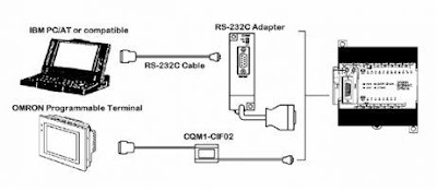
Serial Communication PLC Omron CPM1


Serial communication on this PLC Omron CPM1A generally used for communication PLC with computer or with touch screen from Omron as well. Protocol for communication with a PC is called Host Link Communication (HLC),

HLC can be used for 2 configurations:
a. 1 to 1 communication
b. 1 to N communication

a. 1 to 1 Communication
Form of 1 to 1 Communication looks at the picture below.
1 to 1 Communication plc omron CPM1A

PLC Omron CPM1 requires serial communication module RS 232 (CPM1 called CIF-01) to be able to communicate with other serial devices. Here are the details figures.
serial communication module RS 232 PLC Omron CPM1

Configuration was a serial cable (3 cables) for communications PC - PLC is shown in the picture below.
Configuration serial cable for communications PC - PLC

b. 1 to N Communication
HLC also accommodate communication 1 PC to N PLC (maximum 32 pieces). Protocol used is not 232 RS, but RS 422. The following communication 1 – N scheme.
1 to N Communication

Above scheme using daisy chain network type. In the scheme are also used in different communication modules compare with the previous one, ie RS 422 module adapter (CPM1-CIF11). Detail module appears as below.
RS 422 module adapter

If the type is replaced by a multi drop network, then the scheme will be shaped like the details below.
multi drop network

All the above information can be found in the Programming Manual of the PLC Omron CPM1. Other brands of PLCs will also provide a detailed explanation of the serial communication settings like Omron.
Sponsored Links :

ALL ARTICLES
SUBSCRIBE BY EMAIL:

Delivered by FeedBurner


PLC Simulation Update

Popular Posts

Free Download PLC

Custom Search
Copyright © PLC Ladder