What is Arduino and its function in the control system?
Arduino is basic device in the control system that connecting PLC to appropriate interfaces for I/O. It seems we say that Arduino is act as programmable logic controller (PLC) itself. In this high tech control system, the industrial still use PLC as the basic component of the industrial automation world. But why they still need interface like Arduino to connect I/O and PLC not connecting directly machine with control system? Let’s see why you have to use it as explain below.
The reason why you better use Arduino
In the middle low industries, in fact they need control system to set this production run automatically. But they do not have enough budgets to do that. As you know that the Industrial application made the PLC system has many disadvantages as below:
How can Arduino start work?
we make simple ladder programming, usually Latching Ladder. If Push Button(PB0) is pressed then output (light/motor) latch ON, and if Push Button(PB1) is pressed then output (light/motor) latch OFF.
You can use LDmicro Method to simulate:
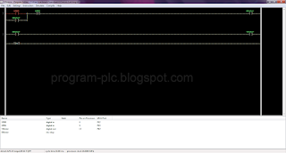
This first thing you have to consider on those control program as mention above is make the ladder code (contact diagram) properly. You can use LDmicro to help your ladder run. This tool can you can executable from the link http://cq.cx/ladder.pl. It is more easy use this tool as shown on figure above.
Or Download my Project File, click here
LDmicro compiles ladder logic to PIC16 or AVR code. The following processors are supported:
* PIC16F877
* PIC16F628
* PIC16F876 (untested)
* PIC16F88 (untested)
* PIC16F819 (untested)
* PIC16F887 (untested)
* PIC16F886 (untested)
* ATmega128
* ATmega64
* ATmega162 (untested)
* ATmega32 (untested)
* ATmega16 (untested)
* ATmega8 (untested)
How to operate LDmicro?:
After download process run successfully, just double click on the LDmicro icon. First you can write a draft of the program that we want to create as diagram above. Basic ladder program knowledge was required on this section. It is easy just use immediate programming approach for the PLC: the wired logic. You do not need complex programming, just use simple Boolean equations algorithm. Digital logic input and output always return as value that can be 0 or 1 code. It means you will use AND for series circuit, the OR for parallel and NOT for negation condition.
Arduino is basic device in the control system that connecting PLC to appropriate interfaces for I/O. It seems we say that Arduino is act as programmable logic controller (PLC) itself. In this high tech control system, the industrial still use PLC as the basic component of the industrial automation world. But why they still need interface like Arduino to connect I/O and PLC not connecting directly machine with control system? Let’s see why you have to use it as explain below.
The reason why you better use Arduino
In the middle low industries, in fact they need control system to set this production run automatically. But they do not have enough budgets to do that. As you know that the Industrial application made the PLC system has many disadvantages as below:
- Being very expensive both to buy and repair
- It also needs highly specific skills technician.
- It requested to software designers to extract the maximum potentials from controllers
- This software has been built for general applications
- It need a little of external hardware, so more practically than others software
- Minimum essentially device is only interfaces to transfer signals from sensors and to actuators, and appropriate software
How can Arduino start work?
we make simple ladder programming, usually Latching Ladder. If Push Button(PB0) is pressed then output (light/motor) latch ON, and if Push Button(PB1) is pressed then output (light/motor) latch OFF.
You can use LDmicro Method to simulate:
 |
| Ladder Diagram Microcontroller |
This first thing you have to consider on those control program as mention above is make the ladder code (contact diagram) properly. You can use LDmicro to help your ladder run. This tool can you can executable from the link http://cq.cx/ladder.pl. It is more easy use this tool as shown on figure above.
Or Download my Project File, click here
LDmicro compiles ladder logic to PIC16 or AVR code. The following processors are supported:
* PIC16F877
* PIC16F628
* PIC16F876 (untested)
* PIC16F88 (untested)
* PIC16F819 (untested)
* PIC16F887 (untested)
* PIC16F886 (untested)
* ATmega128
* ATmega64
* ATmega162 (untested)
* ATmega32 (untested)
* ATmega16 (untested)
* ATmega8 (untested)
How to operate LDmicro?:
After download process run successfully, just double click on the LDmicro icon. First you can write a draft of the program that we want to create as diagram above. Basic ladder program knowledge was required on this section. It is easy just use immediate programming approach for the PLC: the wired logic. You do not need complex programming, just use simple Boolean equations algorithm. Digital logic input and output always return as value that can be 0 or 1 code. It means you will use AND for series circuit, the OR for parallel and NOT for negation condition.
