In this article will discuss the basic instructions Omron PLC. The instructions as below:
1.LOAD (LD), this instruction is used when a work order control system requires only one logic state. This is similar to the NO relay contacts. The symbol is:

2.LOAD NOT, this command is used when a work order control system requires only one logic condition. This is similar to NC relay contacts. The symbol is:

And below are the instructions that are used when the work order control system requires more than one condition and all conditions must be met to produce a single output. The instructions are as follows:
3. AND, the symbol is:

4.AND NOT, the symbol is:

5.OR, the symbol is:

6.OR NOT, the symbol is:

7.OUT, this instruction is used to generate a logic output when the conditions are met. The symbol is:

8.NOT OUT, this instruction is used to generate a logic output when the conditions are met. The symbol is:

9.TIMER (TIM) and COUNTER (CNT), the PLC which amounted to 512 numbers from TC 000 to TC 511. Value of Timer / Counter is counting backwards from the initial value. After reaching zero then contact Timer / Counter will be ON.
The Timer symbol is:

The timer is active when the execution condition is ON and reset when OFF. TIM executed first in order to measure SV 0.1 seconds.
The Counter symbol is:

10.COMPARE-CMP (20), Comparing Cp1 with Cp2 and outputs the results is GR, EQ with the LE flag in the SR area.

11. DIFU (13) Differentiate UP, DIFU (13) makes marked bits ON (0) one cycle when switched from OFF state to ON (leading edge).

12. DIFD (14) Differentiate Down, Turn ON bit (0) one cycle when the condition is switched from ON to OFF.

13. ADD (30) BCD Add, Adding the contents of Au, Ad and Cy, the result is placed in R.

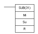
14.SUB (31) BCD subtract, subtracts the contents of Su and CY from Mi and places the result in R. If the result is negative, CY is set and the 10's complement of the actual result is placed in R. To convert the 10's complement to the true result, subtract the contents of R from zero.
