You can assign the data for grasping and changing the inverter’s operation status to D9133 – D9147 and read/write them from the user sequence.
The following data can always be read. They are automatically refreshed every time the END instruction is executed.
1. Operation monitor
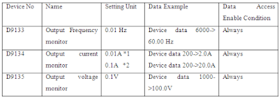
The following data devices are always read- enabled (write-disabled) to allow you to monitor the output frequency, output current and output voltage of the inverter.

2. Error history (error codes and error definitions)
The inverter stores the error codes of the errors that occurred. The error codes of up to eight errors are stored in the order as shown below and are always read-enabled (write-disabled). Errors code storing method details as following:

• Alarm definition read program example.
The following program reads the latest alarm definition of the inverter to D0.

• Regarding the error No. and detail of the self diagnostic errors During execution of a sequence program, any of the following error No. is stored into D9008 due to an operation error. At occurrence of a self-diagnostic error, the P.RUN indication (LED) flickers.
