This application about how to replace PLC analog output module with arduino.
Analog output module generates a voltage between 0 volt to 5 volt.
Analog output module usually used for valve control, fan control, rolling door speed control, elevator speed control, escalator speed control, adjust the brightness of the light, and etc.
This voltage is used to set the frequency of the inverter and controlling the motor speed.
Sample application as shown below:
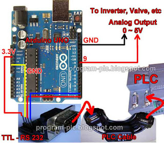
Hardware of PLC analog output module with arduino
- Arduino UNO such as PLC Analog Output Module
- Siemens PLC, Or Others plc with modbus support
- TTL to RS232 Male Module
- PPI to RS232 PLC Cable
- Volt Meter or Multi-tester for Testing
- Power supply for arduino
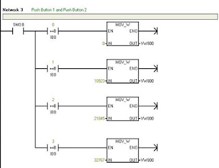
- 2 Pcs Push Botton Switch for test, and connect to PLC input: I0.0 and I0.1
Hardware Connections of PLC analog output module with arduino
Download Project File of PLC Analog Output Module with Arduino
- Download Arduino libraries, click here Copy paste folder SimpleModbusMaster to folder ..\Arduino\libraries
- Download Arduino Project File, click here
- Download PLC Ladder Programming, click here
PLC Ladder Programming of PLC Analog Output Module with Arduino
Arduino Code of PLC Analog Output Module with Arduino
#include <SimpleModbusMaster.h>
//Arduino Serial Port Connect to Port 0 of Siemens PLC S7 200
//for more info program-plc.blogspot.com
#define slaveAddr 1
#define baud 9600
#define timeout 1000
#define polling 200
#define retry_count 0
#define TxEnablePin 2
enum
{
  PACKET1,
  TOTAL_NO_OF_PACKETS
};
Packet packets[TOTAL_NO_OF_PACKETS];
packetPointer packet1 = &packets[PACKET1];
unsigned int readRegs[3];

//ATmega8 only support analogWrite() on pins 9, 10, and 11.
int AnalogOutputPin1 = 9;
int AnalogOutputPin2 = 10;
int AnalogOutputPin3 = 11;


void setup() {
  pinMode(AnalogOutputPin1, OUTPUT);
  pinMode(AnalogOutputPin2, OUTPUT);
  pinMode(AnalogOutputPin3, OUTPUT);
  modbus_construct(packet1, slaveAddr, READ_HOLDING_REGISTERS, 0, 3, readRegs);
  modbus_configure(&Serial, baud, SERIAL_8E1, timeout, polling, retry_count, TxEnablePin, packets, TOTAL_NO_OF_PACKETS);
}

void loop() {
    modbus_update();
    int VW800 = (int)readRegs[0];
    int VW802 = (int)readRegs[1];
    int VW804 = (int)readRegs[2];
    VW800 = map(VW800, 0, 32767, 0, 255);
    VW802 = map(VW802, 0, 32767, 0, 255);
    VW804 = map(VW804, 0, 32767, 0, 255);
    analogWrite(AnalogOutputPin1, VW800);
    analogWrite(AnalogOutputPin2, VW802);
    analogWrite(AnalogOutputPin3, VW804);
}
Video Demonstration: PLC Analog Output Module with Arduino


