PLC, SCADA, Automation, PLC Programming, PLC eBook, Free PLC Training
Home
Donate
Download
Get Free PLC eBook
PLC Programming Examples
Contact Us
Privacy Policy
Follow Me
Home
Donate
Download
Get Free PLC eBook
PLC Programming Examples
Contact Us
Privacy Policy
Follow Me
Wednesday, July 7, 2010
BIN instruction on Omron PLC
BIN instruction on Omron PLC : BCD-To-Binary. Purpose: Converts the BCD contents of S into the numerically equivalent binary bits and o...
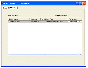
Ladder Logic to Configure EtherMeter – MicroLogix 1100 or 1400
In Rung 0, a self resetting, one second timer is created to setup the polling interval, although a shorter or longer polling interval coul...
Tuesday, July 6, 2010
BCD instruction on Omron PLC
BCD instruction on Omron PLC : Binary-To-BCD. Purpose: BCD(101) converts the binary (hexadecimal) contents of S into the numerically...
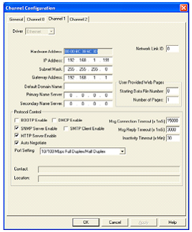
Configuring EtherMeter – MicroLogix 1100/1400
This article will describe to the Allen Bradley Micrologix PLC (1100 or 1400) user who wishes to connect to an EtherMeter using the Ether...
Monday, July 5, 2010
ANDW instruction on Omron PLC
ANDW instruction on Omron PLC : ANDW(130) logically ANDs the contents of I1 and I2 bit-by-bit and places the result in R. Operand Data ...
Configuration of PLC Interfaces for PL Series
The PLC system is used with and external PLC controller, PLC indexer card, or other device in positioning applications. The input connect...
Sunday, July 4, 2010
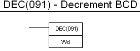
DEC instruction on Omron PLC
DEC instruction on Omron PLC : Decrement BCD Decrements the memory data specified by the operand by 1. Variations: Differentiate Up DEC...
EZPLC the Powerful Ladder Programming
EZPLC is the most innovative PLC in its class. It is packed with power only found in high end PLC’s. It’s also support most flexible I/O ...
Saturday, July 3, 2010
Nano PLCs Editor FTX 117 Terminal
The FTX 117 dedicated terminal is the instruction list language programming tool for Nano PLCs. It is easy to use due to its back-lit scre...
Friday, July 2, 2010
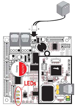
Hardware Connections of EMBEDDED PLC
The hardware connections of EMBEDDED PLC are as following: 1. Connect power supply Connect the AC adapter to header J2, match the fricti...
Thursday, July 1, 2010
EMBEDDED PLC to Program Single Board Computer
EMBEDDED PLC Application Kit is tools to program the BL2500 Single Board Computer (SBC) via ISaGRAF Soft Logic Package. This article will ...
Newer Posts
Older Posts
Home
You may also like these ebook:
Get Free PLC eBook directly sent to your email,
and email subscription to program-plc.blogspot.com
We hate SPAM. Your information is never sold or shared with anyone.
Your Email Will Be 100% Secured !
Your email is stored safely on Google FeedBurner