There are so many applications of PLC especially in industry environment. Here are few examples of PLC programming applications that have ...
Friday, May 7, 2010
Thursday, May 6, 2010
Reading Ladder Logic
Ladder diagrams (sometimes call as Ladder Logic) are specialized schematic commonly used to document industrial control logic systems. The...

Wednesday, May 5, 2010
Push ON Push OFF With Data Memory PLC Mitsubishi
PLC Type FX-Mitsubishi , Name Input / Output PLC : INPUT PLC : X000 ; Push Button Switch ( without lock ). ...

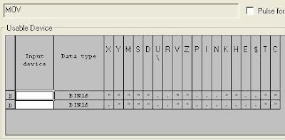
MOV instruction in Mitsubishi PLC
MOV instruction in Mitsubishi PLC : Move The contents of the source device (S) is copied to the destination (D) device when the contr...
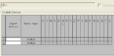
LD= instructions on Mitsubishi PLC
LD= instructions on Mitsubishi PLC : Load compare (Equal) The value of S1 and S2 are tested according to the comparison of the instruc...
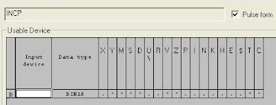
INCP instruction on Mitsubishi PLC
INCP instruction on Mitsubishi PLC : Increment Pulse On every execution of the instruction the device specified as the (D), has its cu...
Allen Bradley PLC Programming Software
This article will explain about the interface between the EPICS crate and the Allen-Bradley PLC using either serial communications through...

Tuesday, May 4, 2010
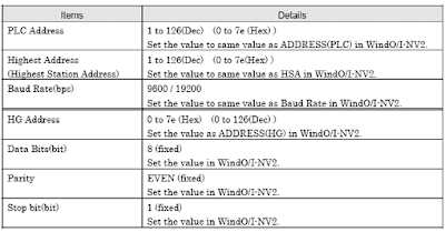
Siemens PLC Addressing
This article will help to configure IDEC touch screens and Siemens S7 PLC using S7-200 protocol. The communications address and port setti...
Monday, May 3, 2010
Telemecanique PLC Direct Addressing
This article is presenting how to connect G3 HMI on a Unitelway network. It is using a proprietary protocol from Schneider Telemecanique. ...

Sunday, May 2, 2010
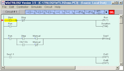
Low Cost Programmable Logic Controller
PLC TRiLOGI is so small and low cost PLC. It can effectively replace all those bulky relays, timers or counters found in their control pan...
Saturday, May 1, 2010
Siemens S7 Connection Configuration
The configuration of Siemens Step7 (S7) is differentiated into 2 connections they are bilaterally configured and unilaterally configured. ...