WAND Instruction on Mitsubishi PLC


WAND instructions on Mitsubishi PLC : source 1 (S1) AND source 2 (S1) , Result in device (D).
The bit patterns of the two source devices are analyzed (the contents of S2 is compared against the contents of S1). The result of the logical AND analysis is stored in the destination device (D).
WAND instructions
illustration of WAND instructions on Mitsubishi PLC:
WAND Hexa 00F0
WAND Hexa 00F0

DECP Instruction on Mitsubishi PLC


DECP instructions on Mitsubishi PLC : Decrement memory with Pulse
Decrements the memory data specified by the operand by 1.
On every execution of the instruction the device specified as the (D), has its current value decremented (decreased) by a value of 1. In 16 bit operation, when -32,768 is reached the next incrementation will write a value of +32,767 to the (D).
DECP instructions
Examples of the use of DECP instructions on Mitsubishi PLC :
DECP ladder Mitsubishi
1. If X000=OFF then Value in D0=30.
2. If X000=ON then Value in D0=29.
3. If X000=OFF then Value in D0=29.
4. If X000=ON then Value in D0=28.
5. If X000=OFF then Value in D0=28.

BIN instruction on Mitsubishi PLC


BIN instruction on Mitsubishi PLC : BCD converted into binary.
The BCD (S) is converted into an equivalent binary number and stored at the destination (D). If the source data is not provided in a BCD format an error will occur. This instruction can be used to read in data directory from thumbwheel switches.
BIN instructions
illustration of BIN instructions on Mitsubishi PLC :
BCD Convert to Binary

BCD instruction on Mitsubishi PLC


BCD instruction on Mitsubishi PLC : binary converted into BCD (Binary-Coded Decimal).
The binary (S) is converted into an equivalent BCD number and stored at the destination (D). If the converted BCD number exceeds the operational ranges of 0 to 9,999 (16 bit operation) and 0 to 99,999,999 (32 bit operation) an error will occur.
BCD instructions
illustration of BCD instructions on Mitsubishi PLC :
Binary Convert to BCD

Writing the Inverter Parameters Mitsubishi PLC


Inverter Parameters Mitsubishi PLC
Parameter writing is performed when the parameter number is stored to D9241 (D9243) and parameter writing value to D9242 (D9244), and turns ON the Y29 (Y2B). When writing is completed, X29 (X2B) turns ON to notify the completion. The device number within parentheses is used to write the parameter setting value to EEPROM. When writing the calibration parameter, set the following value to D9234 (D9235) to write each calibration parameter value.
0: Setting value (Frequency/Torque)
1: Parameter-set analog value
2: Analog value input from terminal

As soon as the inverter parameter write completion (X29(RAM) or X2B (EEPROM)) turns on, 0 is set to D9150 on normal completion. If an error occurs during access to the parameters, e.g. if any value outside the setting range is written or write is performed during inverter operation, the value of parameter No. + H8000 is written to D9150 as soon as the write completion signal (X29(RAM) or X2B (EEPROM)) turns on, resulting in abnormal completion. If abnormal completion occurs, the parameters are not written. For example, if an error occurs in the torque boost, H8000 is written to D9150.

Inverter parameter write must be performed in the PU operation mode or NET operation mode.

Inverter Status Monitoring of FR-A700 PLC


You can assign the data for grasping and changing the inverter’s operation status to D9133 – D9147 and read/write them from the user sequence.

The following data can always be read. They are automatically refreshed every time the END instruction is executed.

1. Operation monitor
The following data devices are always read- enabled (write-disabled) to allow you to monitor the output frequency, output current and output voltage of the inverter.
Operation monitor
2. Error history (error codes and error definitions)
The inverter stores the error codes of the errors that occurred. The error codes of up to eight errors are stored in the order as shown below and are always read-enabled (write-disabled). Errors code storing method details as following:
Error history
• Alarm definition read program example.
The following program reads the latest alarm definition of the inverter to D0.
Alarm definition read program example
• Regarding the error No. and detail of the self diagnostic errors During execution of a sequence program, any of the following error No. is stored into D9008 due to an operation error. At occurrence of a self-diagnostic error, the P.RUN indication (LED) flickers.
detail self diagnostic errors

Sequence Program Writing of Mitsubishi Inverter FR-A700 PLC


Sequence program write can be performed in any operation mode (external operation mode/PU operation mode/Network operation mode). When rewriting the PLC function parameters and sequence program using GX Developer, check the following:
1. Check that the sequence program execution key is in the STOP position (SQ signal is off).
2. Check that the inverter is at a stop.
3. Check that the communication specification setting parameters are set correctly. If any of these parameters are set incorrectly, communication with GX Developer can not be made.
4. Check the PLC series and sequence program capacity in the GX Developer parameters.
5. Refer to the GX Developer manual and write sequence program.

A sequence program can not be written with its step specified. If written, the sequence program does not run. The program outside the specified range is initialized.

Do not read the built in PLC function parameters and sequence program without writing them to the inverter once using GX Developer. Since the inverter does not have normal data, always write the built in PLC function parameters and sequence program once.

Since the built in PLC function parameters and sequence program are written to the flash ROM, there are restrictions on the number of write times, approximately 100,000 times.

1K steps or more can not be written. Number of steps usable when a program capacity is 1K steps are calculated as, 1 X 1024-2 steps = 1022 steps.

Counter C of Mitsubishi PLC Function Programming


The counters of the built-in PLC functions are up counters. An up counter stops counting and its contact turns on when the count value reaches the setting.
1. Count processing
• The coil of the counter is turned on /off at execution the OUT C instruction and its resent value are updated and their contact turns on after execution of the END instruction.
• The counter counts on detection of the leading edge (OFF to ON) of the coil. It does not count if the coil remains on.
2. Counter resetting
• The count value is not cleared even if the coil turns off. Use the RST C instruction to clear the count value and turn off the contact.
• When the counter is reset by the RST instruction, the present value and contact of the counter are cleared at execution of the RST instruction.
Counter Ladder Diagram
The counter counts on the leading edge of the input condition of the counter imported at an input refresh.
counting speed
The maximum counting speed of the counter is determined by the scan time, and the counter can count only when the ON/OFF period of the input condition is longer than the scan time.
Maximum counting speed Cmax = (n/100) x (1/ts) [times/s]
N : Duty (%)
ts : Scan time [s]

Implementation of Neural Network Function Block


The implemented block is a three layer Perception neural network. The block includes three input nodes and seven nodes in second layer and one node in output layer. The block in PLC S7300 has two automatic and manual modes. In the manual mode the parameter of the network are declared manually in the program (W01…W21, B01…B21). They are set by the user when the network is used. However if they are not defined some uniform random number are selected. In the automatic mode parameters of the network are calculated automatically by the back error propagation training method.
Neural Network Function Block
It is the most conventional method for training of these networks. The network is completely trained after almost 10 minutes of the time which the PLC is placed in RUN mode (for 500 data for training). The training data should be sorted in some parts of the PLC memory and it makes a matrix with four vectors including three column vectors as the output date of the network. The input and output data are used for training the network parameters. Every training sequence is calculated in one machine cycle of the PLC system.

Below is diagram of Neural network block output compare to PID output:
Neural network block output compare
To test the designed network in a Siemens PLC, the behavior of a PID controller for a first order simple model is studied in Matlab Software. The model is used to extract data to form four vectors, the samples are gathered from almost 8 minutes analyzing of the PID controller on the model with 1000 sampling points.

Configuring Modicon Telemecanique Quantum 140 NOE IP Address


Before you install your NOE 771 x0 (140 NOE 771 00 or 140 NOE 771 10) module, it needs to be configured with an Internet Protocol (IP) address which can be accomplished by either of the following methods:
• A new user configured IP address which you assign to the module.
• A default address which is derived from the MAC address appearing on the global address label located on the front of the module.

If a new IP address must be assigned, obtain it from your system administrator and then install it using your Concept Programming Panel. Alternately, you may use the BOOTP Server to install the IP address. In either case, record the IP network address on the writable area located on the front panel of the module.

If you use the default IP address derived from the MAC address proceed as follows: Locate the global address label on the front panel of the module. Convert them from hexadecimal to decimal. Each pair of hexadecimal numbers will result in a decimal number between 0 and 225. This is the default IP address.
default IP address
The 140 NOE 771 x0 is capable of communicating over either an auto-sensing 10/100BASE-T or a 100BASE-FX Ethernet network at any given time, but not both at the same time.

Telemecanique Modicon Advance Program TSX7 PLC


The Telemecanique Modicon Advance Program is a simple process to update your legacy systems based upon your specific needs and requirements, allowing you to select the right level of upgrade for your processors, software and I/O points. The program is built around the latest generation of Schneider’s Electric PLC platform and allows you to explore new possibilities that will seamlessly and cost effectively take your automation system to next level.

Schneider Electric’s TSX7 software conversion solutions provide the ability to access the latest non-proprietary communication technologies such as Ethernet TCP/IP. The software converter allows the efficient conversion of your PL7-3 application to Unity Pro, providing the capability to integrate the control system into company wide networks, with diagnostic and process information available through standard we browsers.

If your machine or process has been in service for an extended period of time, your application may have undergone several modifications. As a business with critical processes, you may need to modernize your installation within very short time periods. You may also wish to focus on communication and operating functions with the aid of new software developments.

With Modicon Advance Program TSX7 PLC, it will help to control the risk of upgrading which is a major benefit when modernizing your system.

Modicon Telemecanique Unitelway Network with G3


This article presents how to connect G3 HMIs on a Unitelway network. This network is using a proprietary protocol from Schneider telemecanique. The PLCs are also known as Square D or Modicon. As cabling particular for Unitelway, this note will describe on the connections between the HMI and the PLCs and between the PLCs.
HMI and PLC
As the Unitelway network supports only one master, both G3 will be slaves. Therefore the communication driver Unitelway Slave will be used in Crimson 2.0 configuration.

G3 Connections on the Network
In order to get data exchange, two cabling solutions are available:
1. Using the TER and AUX ports of the PLCs.
Telemecanique PLCs have 2 communication ports on the front panel. They are actually on the same network and can be used for easy connections to create the network.
G3 Connections Network
2. Cabling as a unique bus
In this solution, cabling will be the same on a pin to pin point of view, only the connection point will be different. It will be as below:
G3 Cabling unique bus
In order to get this network up on running, the G3 have to be programmed as followed:
1. Select Unitelway Slave protocol.
2. Choose right Baud Rate, parity and stop bits as defined by the network.
3. Define the TSX as a Master.
4. Enter the G3 address on the network. This address has to be different from the others slaves and can not be 1, 2 or 3 as they are reserved by the master.
5. Indicate the address of the unit you wish to communicate with. An address of 0 will access the master. You can access other slaves as well if you enter their address.

Defining the Access Names of TELEMEC Server with InTouch


InTouch uses Access Names to reference real time I/O data. Each Access name equates to an I/O address, which can contain a Node, Application, and Topic. In a distributed application, I/O references can be set up as global addresses to a network I/O Server or local addresses to a local server.

The following fields are required entries when entering Access Name Definition:
Access Name Definition
1. Access Name
In the Access Name box type the name you want InTouch to use to this Access Name.
2. Node Name
If the data resides in a network I/O Server, in the Node Name box, type the remote node’s name.
3. Application Name
In the Application Name box, type the actual program name for the I/O server program from which the data values will be acquired. In case the values are coming from the TELEMEC Server the TELEMEC is used. Do not enter the .exe extention portion of the program name.
4. Topic Name
Enter the name defined for the topic in the TELEMEC Server to identify the topic the TELEMEC Server will be accessing.
5. Protocol to use
Select the DDE Protocol.
6. Advise Server
Select Advise All Items if you want the server program to poll for all data whether or not it is in visible windows, alarmed, logged, trended or used in a script. (Not recommended).
Select Advise only active items if you want the server program to poll only points in visible windows.

Telemecanique Dynamic Data Exchange (DDE) Server


The Telemecanique DDE Server is a Microsoft Windows application program that acts as a DDE (Dynamic Data Exchange) server and allows other Widows application program to access the data from the Telemecanique TSX17-20 micro PLC and its I/O extensions blocks. Connection requires a TSX17 ACC8 interface cable and a TSX 17 ACC11 connection kit with the 9 and 25-pin connectors. The data link is established by connecting TSX 17 ACC11 to the 9-pin serial port on the IBM PC and to the 25 pin connector on the TSX 17 ACC8 is set to the Series 7 position.

The DDE protocol identifies an element of data by using a three-part address, including Application, Topic, and Item.

Application refers to the name of the Windows program (server) that knows how to access the data element. For the TELEMEC server, the application portion of the DDE address is TELEMEC.

Topic is an application specific sub group of data elements. The TELEMEC server considers Micro PLC and uses this name as the topic name for DDE references.

Item indicates a specific data element within the specified topic. For the TELEMEC Server, an item is Input bit, output bit, System bit, Internals word, Constant word, System word, Input register word, output register word, bit of any word, parameter of function block.

Timer Countdown with PLC Mitsubishi


PLC Type FX-Mitsubishi , Name Input / Output PLC :

INPUT PLC :
X000 ; Toggle Switch ( ON - OFF ).

OUTPUT PLC :
Y000 ; OUT0 or Seven Segment A of Digit 1.
Y001 ; OUT1 or Seven Segment B of Digit 1.
Y002 ; OUT2 or Seven Segment C of Digit 1.
Y003 ; OUT3 or Seven Segment D of Digit 1.
Y004 ; OUT4 or Seven Segment E of Digit 1.
Y005 ; OUT5 or Seven Segment F of Digit 1.
Y006 ; OUT6 or Seven Segment G of Digit 1.
Y007 ; OUT7 or Seven Segment A of Digit 2.
Y010 ; OUT8 or Seven Segment B of Digit 2.
Y011 ; OUT9 or Seven Segment C of Digit 2.
Y012 ; OUT10 or Seven Segment D of Digit 2.
Y013 ; OUT11 or Seven Segment E of Digit 2.
Y014 ; OUT12 or Seven Segment F of Digit 2.
Y015 ; OUT12 or Seven Segment G of Digit 2.
Y016 ; Lamp to signal countdown completion.

PLC Programming for Timer Countdown with PLC Mitsubishi


Reading Ladder PLC Programming for Timer Countdown with PLC Mitsubishi :

Step 1 :
Setting Timer T0 = 1 Second
Decrements the memory data specified by the operand by 1
a.If X000 = ON And M32 = OFF And T0 = ON Then Decrement D0 ( DECP / Decrement Pulse).

Step 2 :
a.If X000 = OFF Then D0 = 30 ( MOV K30 D0 ).
b.If D0 = 0 Then M32 = ON And Y016 = ON.

Step 3 : Determine digit1 and digit2
Digit1 : 0 -- 1 -- 2 -- 3 -- 4 -- 5 -- 6 -- 7 -- 8 -- 9
Digit2 : 00 -- 10 -- 20 -- 30 -- 40 -- 50 -- 60 -- 70 -- 80 -- 90
a.Convert to BCD (BCD D0 D100) --> AND with Hexa 000F (WAND D100 H0F D101) --> Convert to Binary (BIN D101 D1)
b.Convert to BCD (BCD D0 D103) --> AND with Hexa 0F0 (WAND D103 H0F0 D104) --> Convert to Binary (BIN D104 D2)

Example : Value D0 = 29
-->If D0 = 29 Then D1 = 9 And D2 = 20.

Step 4 : digit1
a.If D1 = 0 Then M0 = ON.
b.If D1 = 1 Then M1 = ON.
c.If D1 = 2 Then M2 = ON.
d.If D1 = 3 Then M3 = ON.
e.If D1 = 4 Then M4 = ON.
f.If D1 = 5 Then M5 = ON.
g.If D1 = 6 Then M6 = ON.
h.If D1 = 7 Then M7 = ON.
i.If D1 = 8 Then M8 = ON.
j.If D1 = 9 Then M9 = ON.

Step 5 : digit2
a.If D2 = 00 Then M10 = ON.
b.If D2 = 10 Then M11 = ON.
c.If D2 = 20 Then M12 = ON.
d.If D2 = 30 Then M13 = ON.
e.If D2 = 40 Then M14 = ON.
f.If D2 = 50 Then M15 = ON.
g.If D2 = 60 Then M16 = ON.
h.If D2 = 70 Then M17 = ON.
i.If D2 = 80 Then M18 = ON.
j.If D2 = 90 Then M19 = ON.

Step 6 : Output digit1
a.If M0 = ON Then Y000= ON And Y001 = ON And Y002 = ON And Y003 = ON And Y004 = ON And Y005 = ON.
b.If M1 = ON Then Y001 = ON And Y002 = ON.
c.If M2 = ON Then Y000= ON And Y001 = ON And Y003 = ON And Y004 = ON And Y006 = ON.
d.If M3 = ON Then Y000= ON And Y001 = ON And Y002 = ON And Y003 = ON And Y006 = ON.
e.If M4 = ON Then Y001 = ON And Y002 = ON And Y005 = ON And Y006 = ON.
f.If M5 = ON Then Y000= ON And Y002 = ON And Y003 = ON And Y005 = ON And Y006 = ON.
g.If M6 = ON Then Y000= ON And Y002 = ON And Y003 = ON And Y004 = ON And Y005 = ON And Y006 = ON.
h.If M7 = ON Then Y000= ON And Y001 = ON And Y002 = ON.
i.If M8 = ON Then Y000= ON And Y001 = ON And Y002 = ON And Y003 = ON And Y004 = ON And Y005 = ON And Y006 = ON.
j.If M9 = ON Then Y000= ON And Y001 = ON And Y002 = ON And Y003 = ON And Y005 = ON And Y006 = ON.

Step 7 : Output digit2
a.If M10 = ON Then Y007 = ON And Y010 = ON And Y011 = ON And Y012 = ON And Y013 = ON And Y014 = ON.
b.If M11 = ON Then Y010 = ON And Y011 = ON.
c.If M12 = ON Then Y007 = ON And Y010 = ON And Y012 = ON And Y013 = ON And Y015 = ON.
d.If M13 = ON Then Y007 = ON And Y010 = ON And Y011 = ON And Y012 = ON And Y015 = ON.
e.If M14 = ON Then Y010 = ON And Y011 = ON And Y014 = ON And Y015 = ON.
f.If M15 = ON Then Y007 = ON And Y011 = ON And Y012 = ON And Y014 = ON And Y015 = ON.
g.If M16 = ON Then Y007 = ON And Y011 = ON And Y012 = ON And Y013 = ON And Y014 = ON And Y015 = ON.
h.If M17 = ON Then Y007 = ON And Y010 = ON And Y011 = ON.
i.If M18 = ON Then Y007 = ON And Y010 = ON And Y011 = ON And Y012 = ON And Y013 = ON And Y014 = ON And Y015 = ON.
j.If M19 = ON Then Y007 = ON And Y010 = ON And Y011 = ON And Y012 = ON And Y014 = ON And Y015 = ON.

Please Download Programming for GX Developer :
Timer Countdown with PLC Mitsubishi

See : Timer Countdown

Topic Definition Command of TELEMEC DDE Server


When the TELEMEC DDE server starts up, it first attempts to locate its configuration file by checking the WIN.INI file for path that was previously specified. If the path is not present in the WIN.INI file, the server will assume that the current working directory is to be used.

To start the server from an application directory configuration file other than the default configuration file a special switch is used. For example, invoke the File/Run command in File Manager or Program manager and enter the following:
TELEMEC /d:c:\directoryname

The user provides a connected micro PLC with an arbitrary name that is used as the DDE topic for all references to this PLC.
The following steps are taken to define the Topic attached to the PLC:
1. Invoke the Topic Definition…command. The Topic Definition dialog will appear:
Topic Definition
2. To modify existing topic, select the topic name and click on Modify. To define a new topic, click on New. To remove an existing topic, click on Delete. The “TELEMEC Topic Definition” dialog will appear:
TELEMEC Topic Definition
3. Enter the Topic Name, which corresponds, to the DDE Topic Name (The DDE Topic Name is entered in the ”DDE Access Name Definition” dialog box described in the Using the TELEMEC Server with InTouch section).

4. Click on the Com Port button to associate a topic with the communication port. Note: Additional topic may be associated with the same communication port later.

5. Set the Update Interval field to indicate the frequency the items/points on this topic will be read (polled). Default value is 1000 milliseconds.

When all entries have been made, click on OK to process the configuration for this topic.

Connecting SOI-120 & SOI-260 to the GE Fanuc PLC


The SOI may be connected to the GE Fanuc PLC via the programming port or one of the SNP capable ports in an optional GE Fanuc Communications Coprocessor Module, Contact spectrum controls for information on interfacing to the CMM using Modbus protocol.
GE Fanuc Communications Port DB15
series 90-30 CMM 311 Port 2 DB25
The PLC communication port receive data differential pair must be terminated as indicated if the PLC is either the first or last drop on the SNP bus. This always the case in the point-to-point configuration. However, PLCs may be connected as multiple drops. Do not connect the termination resistor if the PLC is not the first or last drop on the SNP bus.

Shield Ground
The shield must be grounded at the first drop on the SNP bus. If the SOI is the first drop on the bus, connect the SOI communication port pin 5 and 9. If the PLC is the first drop on the bus, connect pins 1 and 7 on the PLC port. Do not connect the shield to ground on more than one unit (PLC or SOI) on the SNP bus. SOI Resistor termination.

The SOI communication port receive data differential pair must be terminated as indicated if the SOI either the first or last drop on the SNP bus. Do not connect the termination resistor if the SOI is not the first or last drop on the SNP bus. The SOI will only connect to and communicate with one PLC regardless of how many are attached to the SNP bus.

Cabling and Communication Port of GE Fanuc PLC SOI-120 & SOI-260


This article covers the information needed to use an SOI-120 or SOI-260 operator interface product with a GE Fanuc Programmable Logic Controller.

GE Fanuc SNP Communications Reference covers the cabling needed to use the SOI-120’s RS-232 communications port as shown in figure 1.1 and the SOI-260’s communications port and optional printer port as shown in figure 1.2.
communications port
Use the communication ports to:
• Upload or download application programs from a personal computer.
• Connect your SOI-120 or SOI-260 to the programmable controller.

On the SOI-260, you can also use the optional RS-232 printer port to:
• Output Printer Forms to a printer or other serial device, such as a large ASCII display unit.
• Accept data from an ASCII input device such as a bar code scanner.

On the SOI-260, you may use either the communications port or the optional printer port to upload or download application program from personal computer. On SOI-120 you must use the communications port.

Figure 1.3 and 1.4 show the cable pin connections (9 pin to 25 pin and 9 pin to 9 pin, respectively) when using SOI-120’s or SOI-260’s communications port (RS-232 selected) to upload or download applications from a personal computer. The figures indicate the required connections when building your cable.
Upload or download cable for 25-pin computer connections
Upload or download cable for 9-pin computer connections

Interface between Operating System and Interrupt Service Routine of PLC 135 WB


PLC 135 WB has interrupted processing capabilities. In this mode, the cyclic program in interrupted and an interrupt service routine executed. Once the interrupt service routine has terminated, the processor returns to the point of interruption and resumes execution of the cyclic program.

The interrupt service routine is initiated in two different ways:
• I/Os causing interrupt (OB 2).
• Signal state change of selected input bit (edge-controlled) (OB 3).

OB 2 and OB 3 constitute the interface between the operating system and the interrupt service routines.

Organization block OB 2
OB 2, the block with the highest priority, is called by interrupts of the process I/Os causing the interrupt. It can only be processed in special mode. The alarms are retained in flag bytes FY 8 to FY 10 and must be acknowledged by the user.

Organization block OB3
OB 3 is always invoked when the signal state of a bit in up to four interrupt input bytes changes. The user may select the input bytes and default it via machine data (PLC MD 124 to 127).

The system program checks the interrupt bytes every 10 ms, and invokes an interrupt service routine when required. OB 3, however, is only processed once per 10 ms scan, even, if several signal state change occur.

OB 3 can be processed in normal or special mode and has a lower priority than OB 2, e.g.
OB 3 can not interrupt OB2.

Unity Pro is Programming, Debugging, & Operating Software for Modicon PLCs


Unity Pro is the common IEC 61131-3 programming that produced by Telemecanique, debugging and operating software for Modicon Premium, Atrium and Quantum PLCs.

Base on the acknowledged standard of PL7 and Concept, Unity Pro opens the door to a comprehensive set of new functions for achieving greater productivity and software collaboration.

Integrated converters, PL7 and Concept IEC applications are available in Unity Pro. This optimizes your software investment, reduces training costs and offers unrivaled potential for development and compatibility.

The application objects directly reflect the application specific components of the automated process, memory independent symbolic variables, structure data and user function blocks.

Stores in libraries on the local PC or remote server, the application objects and their properties are used and shared by all programs. Programs are automatically outdated if a library object is modified.

Five IES61131-3 languages supported as standard with high performance graphic editors and complete sets of system and application debugging and diagnostics functions.

PLC simulator on the PLC enables applications to be fully tested before being installed on site. Hyperlinks enabling all the documents and tools required for user intervention during operation or maintenance to be linked to the application.

Immediate diagnostic with a display window which provides a clear display of all system and application faults in chronological order. The navigation function for finding the causes of faults traces missing conditions back to the sources.

Modicon 800-Series Input/Output Modules


The Modicon 800-Series input/output offer one of the industries widest ranges of I/O modules. Their dependability has been proven in thousands of application worldwide. With over 50 modules to choose from, you can select the most cost-effective module for field device requirements.

The Modicon I/O family offers discrete, analog, special purpose and intelligent modules to meet the most demanding I/O and process control needs:

• Discrete In – which convert signals coming from field input devices such as push buttons, limit and proximity switches, or photo sensors into signals that can be used by the PLC.

• Discrete Out – which convert signals generated by the PLC into output signals used to control field devices such as motor starters, relays, lamps, or solenoids.

• Analog In – which convert analog signals coming from field input devices such as pressure, level, temperature, or weight sensors into numerical data that can be used by the PLC.

• Analog Out – which converts numerical data generated by the PLC into analog output signals to be used by field devices – such as heaters, valves, pumps instrumentation, or drives.

• Special Purpose – which handle unique signal requirements. For instant high speed counter, CAM emulator, RTD and thermocouple modules.

• Intelligent – designed for unique field applications that require i-directional (in/out) capabilities and on board processing power. For instant an ASCII/BASIC Module and high speed logic solver.

Modicon B882-239 High Speed Counter Module


The B882-239 High Speed Counter Module has two identical and independent counters for applications that require counting or comparisons. Because the module handles the counting within own internal logic, the PLC is free to do other tasks.

Each counter counts to 9999, and two counters can be cascaded to count to 99,999,999. Each counter counts up to 10,000 pulses per second. The module has two modes of operation, high frequency and low frequency, so its maximum count rate varies from 350 Hz (Low Frequency) to 30 KHz (High Frequency).

Because the module acts independently of the PLC, it counts the high speed pulses from the field independently of the PLC scan. The counter automatically reports its current count to the PLC every scan. Where high performance is required, the modules own outputs can trigger independently of the controller scan.

The major features of the B882-239 High Speed Counter Module include:
• Two independent counter (0 – 32 Vdc, true Low).
• 0 – 30 KHz operation with selectable low frequency filter.
• Six auxiliary field inputs (0 – 32 Vdc, True Low).
• Six Field outputs (0 – 32 Vdc, True Low).
• Self diagnostic.
Other specifications of Modicon B882-239 High Speed Counter Module are:
• Reset Pulse width 13us (min).
• Enable set up time
High Frequency mode: 11us (max).
Low Frequency mode: 13us (max).

ProWORX 32 Programming Software for Modicon PLC


ProWORX 32 programming software is a full featured, Modicon PLC programming software that compatible Windows platform (98/NT/2000/XP) that gives you the power to program all your Modicon controllers online or offline, manage your I/O subsystems, and analyze your plant activities in real time.

Below are the benefits of ProWORX 32 for Modicon PLC:
• Conversion
484 to984 in one step. The most flexible conversion tools available in automation project while it is running live. With the ability to convert from older project databases to this latest tool ProWORX already support PLC heritage for few decades.

• Intuitive Register Editor.
A power analysis tool, the data watch Windows shows you information from your plant in real time, or logs it to disk for in-depth historical analysis later on. Easily get the data you need to make informed, effectives production decisions.

• I/O Drawing Generator.
Save hours of painstaking effort with ProWORX 32’s I/O Drawing Generator, which automatically creates wiring diagrams for the I/O cards defined in the Traffic Cop. Generate necessary drawings all at once or just one card at a time-simply select an address I/O card uses with the Network Editor, then click the drawing button the hardware back referencing panel to display the diagram, save it as AUTOCAD-compatible.

S908 Remote I/O Processor for Modicon PLC 984-685/785


Remote I/O is the portion of the controller’s I/O that is typically installed away from the PLC housing and that requires an interface module to communicate with the I/O processor at the CPU. Communication to the primary housing at each drop is accomplished through coaxial cable. A remote I/O system may consist of single or multiple housing at each drop.

The S908 Remote I/O Processor Option Module provides remote I/O capability to the 984-685/785 controller lines. Using the S908 remote I/O processor, these controllers can address up to 31 remote drops of 800-series I/O. In addition, each drop can support two ASCII communication ports (maximum of 32 ports available). S908 processors are available with either one or two coaxial cable connectors for single or dual cable configurations.

The S908 Remote I/O Processor occupies one option slot in a 984-685/785 controller. A 785upgrade kit is available to support a 16 drop Quantum I/O S908 network. The AM-E785-QK0 kit includes:
• 785 downloadable executive, #SW-E785-Q00.
• S908 16 drop cartridge, #AS-Q908-016.

This 785 upgrade kit supports up to 16 drops of 800 series I/O and Quantum I/O. Each drop must be either 800- series I/O or Quantum I/O. A combination of 800-Series I/O and Quantum I/O is not supported within a drop. The local drop supports only 800-series I/O.

ProWORX NxT Software Programming for Modicon PLC


ProWORX NXT is produced by Schneider Electric, The simple cross platform programming solution for Modicon PLCs. This leading edge software gives you the power to program all your Modicon controllers, online or offline, manage your I/O subsystems, and analyze your plant’s activity in real-time, all in a familiar Windows environment.

It is the only programming software you will need for your Modicon PLCs. It is compatible with the Modicon Micro, Compact, 584, 984, Quantum and Momentum.

This programming software is common programming environment that will simplify and speed up your system development and commissioning time.

Below are the advantages of ProWORX NxT programming software:
1. Reduce development time and effort
It reduces development time by using the same commands and instructions for every controller.
2. Real-time network status
ProWORX NxT has powerful Network Scan feature. Network scans searches your Modbus then identifies and graphical displays each device found and shows its status.
3. Advanced I/O Management
Ensure that the I/O card you are configuring in the software matches the one on your plant floor with ProWORX NxT’s graphical traffic cop. It displays I/O cards on your screen the same way they look in real life, eliminating all confusion.
4. Easy Subsystem Configuration
Using the new Wizards now included in NxT, The user is stepped through complicated communication configuration with ease.

Basic Physical Configuration of Modicon 984 PLCs


Modicon 984 PLCs are designed as a compatible family, the individual products in the family offer a wide range of functionality and physical attributes. This means you can use the right PLC for the right job – no matter what application.

The PLC is available in three basics physical configurations: compact, chassis mount and slot mount. Slot mount PLCs use an advance microprocessor architecture that incorporates system and power components into single compact modules. These modules mount in the primary 800 Series I/O sub racks. They include the 984-38x series. 984-48x series, 984-685 series, and 984-785 series PLCs. These models cover small to large control applications with logic solve time ranging from 1.0…5 milliseconds/K of user logic. Slot mount PLCs are the perfect choice for small to large applications such as machine or process control.

Chassis mount PLCs are housed in rugged four or seven slot chassis. These PLCs comprise a set of modular system boards that are individually installed in slots in the chassis. Chassis mount PLCs include the 984A, 984B, and 984X models. These models cover mid range to extra large control application with high performance logic solve time of about 0.75 milliseconds/K of user logic.

General 984 Environmental specifications as following:
• Ambient Temperature : 0 – 60oC , 32 – 140oF
• Humidity : 0 – 95% non condensing
• Shock : 10 G’s for 11 msec
• Vibration : .625 @50 – 500 Hz
• RFI/EMI Emission : Complies with applicable FCC requirements
• RFI/EMI Susceptibility : ML-STD-461B; CS02-Conducted; RS03-Radiated
• UL Listing :E54088
• CSA Listing : LR32678

On-Screen Cross Reference of SYSWIN


Select Block Cross reference command to display the Address Cross reference dialog. Using the Display options, you can choose to display the list of addresses used within the current network (Alt+F7) or you can display the complete list of addresses used within the whole program (Alt+F8). When you are editing the program in the ladder editor you can press Alt+F6 to quickly show the cross references for the current address at the cursor.

Find Address
You can quickly find the references for any address by typing in the Find Address field.

Previous/Current/Next
If you choose to display the address list for the current network, you can use the Next and Previous buttons to change the current network. If you have changed the current network by clicking on cross-references, you can update the Address list by clicking the Current button.

Go To
If you have a cross reference entry highlighted, you can close the Address Cross References and edit the current network using the ladder editor by pressing the Go To button. A quicker way to edit the current network is to double click on the highlighted cross reference entry.

Close
This button closes the Address Cross-Reference and returns you to the original network that you were editing before you started the Address Cross References.

Statement List Editor in PLC with SYSWIN


The actual PLC instruction code which underlies any ladder program can be viewed and edited with the Statement List Editor. It allows you to verify the contents of networks in instruction format, and make changes as necessary. You can use Statement List Editor to create an entire program, through the features of SYSWIN encourage more intuitive programming method using ladder diagrams. This editor is intended to enable the viewing and modification of networks when the need arises.

Statement List Editor The Statement List Editor is opened with command from the Editors menu, or by clicking on the Statement List Editing button on the toolbar (Ctrl+F8). This dialog operates with the ladder display, so that when you move between networks, the ladder display moves too, and always shows the same network as selected in the editor. Use the Previous and Next buttons to step from one network to the next.

The Network and name fields from the current network header are displayed-the name field can be changed with the Network Symbol Editor.

The instruction list can be displayed in either address or symbolic format, depending on your selection for the Display option. If you have used the other editors to create symbol names for addresses, the information displayed here in Symbol mode makes it easier to follow the instruction listing. You can only change between display modes when the instructions are valid.

Instructions are entered as normal text, similar to Notepad. You can use the Windows cut, copy, paste tools (Ctrl+X, Ctrl+C, and Ctrl+V) in the usual way to edit the list, and the mouse to select items for coping or deleting. Ctrl+Z can also be used to undo the last change.

Entering Functions on PLC Projects with SYSWIN


All ladder programs use function in addition to the basic instruction. These are entered in much the same way as symbols, but because most of them require data parameters on which to operate, the process involves different dialogs.

SYSWIN uses your setting of the PLC type, together with your function mapping parameters to determine which functions are available to use. When a function is selected, a dialog box is displayed requesting the necessary data.

If you know which function you wish to insert in a network, the easiest way to enter it is to use the ‘F’ key. This displays the function dialog box, and you can type in the name or number of the function.

When a function is drawn, its inputs (and occasionally output) are indicated by unterminated lines. These need to be connected to other parts of the network before the network is complete.

Most functions are available in differentiated and non-differentiated forms. They identified by special symbols in front of the name. When a function can have more than one form, the dialog provides extra check boxes. Alternatively, you can use special characters when typing a function name, and SYSWIN converts the function as appropriate:
• @ Differentiate UP
• % Differentiate DOWN
• ! Immediate refresh

The availability of differentiated functions, contacts and outputs depends on the PLC type.

TBIN instructions on Keyence PLC


TBIN instructions on Keyence PLC : Transfer BIN.
Converts the content of [Acc (internal register)] to binary.
TBIN instructions
illustration of TBIND instructions :
BCD Convert to Binary

TBCD instructions on Keyence PLC


TBCD instructions on Keyence PLC : Transfer BCD (Binary-Coded Decimal).
Converts the content of [Acc (internal register)] to BCD (Binary-Coded Decimal).
TBCD instructions
illustration of TBCD instructions :
Binary Convert to BCD

DEC instructions on Keyence PLC


DEC instructions on Keyence PLC : Decrement memory
Decrements the memory data specified by the operand by 1.
DEC instructions
Examples of the use of DEC instructions :
DEC ladder keyence
1. If 0000=OFF then Value in DM0000=30.
2. If 0000=ON then Value in DM0000=29.
3. If 0000=OFF then Value in DM0000=29.
4. If 0000=ON then Value in DM0000=28.
5. If 0000=OFF then Value in DM0000=28.

ANDA instructions on Keyence PLC


ANDA instructions on Keyence PLC : AND A [Acc (internal register)].
Calculates the logical AND of the operand the content of [Acc (internal register)].
[Acc] AND[operand] --> [Acc]
ANDA instructions
illustration of ANDA instructions :
ANDA Hexa 00F0
ANDA Hexa 00F0

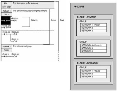
Program Structure of SYSWIN in a PLC Project


Although it is possible to create a program that consists of a simple series of networks, SYSWIN encourages you to break down a program into groups of networks, which form functional blocks.

The concept programming in block is designed not only to make it easier for you to work through a program, by splitting it into manageable chunks, but also to maintain the program after it has been in use for a while. Programming in blocks also eases the process of creating library modules that can be incorporated into future programs.

SYSWIN encourages the creation of groups of networks within blocks, again promoting the concept of working in a structured manner, as shown in this example:
Program Structure
With CV series PLCs, interrupt routines are held in separate blocks, and main blocks are sequential and joined together. For both C and CV series, the last block in main program must contain the END instruction, as normal.

Normally you would not be connected to the PLC when preparing the main structure of a program. After programming you would check the program carefully before connecting and downloading it to the PLC. Checking of program syntax and validity of function is done by SYSWIN at various times as a protective mechanism, but any logical checking that you do speed up the debugging process.

CPM1A Programmable Logic Controllers General Feature


The following lists are CPM1A PLC features: • The CPM1A is a compact PLC with 10, 20, 30 or 40 I/O terminals built into the CPU.
• An expansion I/O unit can be connected to the 30 and 40 I/O point CPU to add an extra I/O point.
• Flash memory provides memory backup without a battery.
• The CPM1A-10CDR PCs can handle 2 interrupt inputs, the CPM1A-20CDR-CPM1A-30CDR and CPM1A-40CDR PCs can handle 4 interrupt inputs. In addition to normal input interrupts, the CPM1A has a counter mode that counts high-speed input signals and triggers interrupts at fixed count multiplies.
• Quick response input can detect input signals with a pulse width as short as 0.2 ms regardless of their timing during the PLC cycle. Quick response inputs and interrupt inputs use the same input terminals.
• CPM1A PLCs have a high speed interval timer which can be used in incremental mode or up/down mode. The high speed counter can be combined with input interrupts to perform target value control or zone comparison control that is not affected by the PLC’s cycle time.
• The CPM1A PLCs have 2 analog volume controls that can be used to make manual analog settings manually.
• The CPM1A PLCs are compatible with Host Link.
• An RS-232C adapter is used for 1-to-1 communications and an RS-422 adapter is used for 1-to-n communications.
• A data link can be created with the LR data area.
• High-Speed Man-Machine interface operations can be achieved by connecting the CPM1A to the Programmable Terminal through the NT Link Interface.
• The CPM1A uses the same Programming Consoles and SYSWIN Programming software.

SYSWIN V3.4 Features and Controller Link Network Support


This new version of SYSWIN V3.4 offers increased functionality for the creation and testing of PLC programs and increases the range of PLCs supports. The features of SYSWIN V3.4 are as following:
• Support for the SYSMAC ALPHA PLCs with 3 digit Expansion Functions.
• Controller Link Protocol Support.
• Communications with C-series PLC using Ethernet via the PCMCIA interface.
• Communication with a CV-series PLC using Ethernet.
• Communications with a PLC via a C200H Bridge using SYSLINK.
• Import and export of data between SYSMAC-CDM and SYSMAC-SCS.
• CV memory card support.
• Error history log.
• Project password protection.
• Program password protection.
• Unit setup.
• Advanced installations.
• Support for updates to C200HX (CPU65 and CPU85).
• Additional PLC setup for C series PLCs.
• Additional CV I/O table support.
• Memory card support for CV series PLCs to allow for partial download.

SYSWIN additionally supports the Controller Link network. The Controller network is an FA network that can send and receive large data packets flexibly and easily among the Omron C200HX/HG/HE PLCs, CV series PLC and IBM PC/AT or compatible computers.

The Controller Link supports data links that enable data sharing and a message service that enables sending and receiving data when required. Data link areas can be freely set to create a flexible data link system and effectively use data areas.

Omron SYSWIN for Creating Programs of PLC


The Omron SYSWIN software is designed for use with SYSMAC C and CV series Programmable Logic Controllers (PLCs). It provides straightforward method of creating and maintaining programs and testing their operation, either offline or connected to a PLC.

SYSWIN offers a comprehensive range of facilities for the PLC programmer, from program editing to full symbolic and network debugging, including:
• New program creation.
• Program storage and editing.
• Uploading and downloading code to a PLC.
• Program status during execution by PLC.
• Commenting programs: Symbolic addresses; Symbolic blocks and network frames; Comments.
• Maintenance of library files.
• Printing program and documentation.
• Conversion from other packages.

SYSWIN runs in the Microsoft Windows environment (version 3.1 and greater) on standard IBM and compatible 486 and Pentium based desktop computers. SYSWIN is intuitive to use, and allows the programmer to rapidly configure a specific project and enter network and program data. PLC programs can be constructed in either ladder or function plan format, and previously tested networks can be recalled from libraries. A special statement list editor allows PLC programs to be viewed and checked in their mnemonic format.

These features are designed to enable users to easily adapt PLC programs to changing requirements. Additional features allow the testing of new networks in supportive and safe environment.

System Requirement to Operate SYSWIN


SYSWIN operates on IBM and compatible personal computers with 80486 or better central processors, including Pentiums. It should be possible to fully install SYSWIN on any computer that can run Windows 3.1 software.

The following configuration is recommended as a minimum system for running SYSWIN effectively:
• 50 MHz 80486 or better CPU, running in enhanced mode (90 MHz Pentium processor is recommended.
• At least 8 Mbytes RAM (16 Mbytes RAM recommended or 32 Mbytes for Microsoft NT users).
• Hard disk storage with at least 10Mbytes of free space.
• VGA or better display system (800 x 600 SVGA or higher resolution is recommended).
• Microsoft Windows 3.1 or higher (Microsoft Windows 3.11 for Workgroups is recommended).

It is possible to run SYSWIN in CPM1 or Demonstration mode on any machine that can run Windows software. If you intend to connect a PLC to the computer for executing program code and testing, you will require:
• RS-232C connection via a standard serial port on the computer (COM1 etc), or
• RS-442 connection, or
• SYSMAC-LINK Network service board, or
• SYSMAC-NET Network Service Board, or
• Controller Link Service Board, or
• Ethernet.
Refer to the appropriate hardware system manuals for full information about connecting and configuring these devices for your environment.

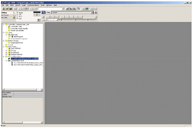
Ladder Programming Workspace of SYSWIN


The main area of the SYSWIN screen is devoted to the ladder program display, as a window covering part of the total programming workspace. To view larger portion of the workspace, you can use Preferences Overview Mode command-selecting this same command again switches back to normal mode.

When first running SYSWIN, or opening a program you always see the left-hand ‘rail’, from which ladder program networks always begin. A right-hand rail exists in workspace, at its extreme right, but this is normally off the screen. When you complete the network, outputs are drawn showing a small vertical bar to indicate the right rail. This saves having to scroll the display to see the right-hand side of your networks.

The currently selected network is generally displayed at the top left of the workspace window. The left-hand side of the power is highlighted and the program scroll as you move up and down between networks. SYSWIN has a keyboard interface that allows the Up and Down arrow keys to roll up and down between networks. Page Up and Page Down keys scroll the screen by full pages. Block Insert Network command (Alt+Insert) enables you to create a new network, above or below the selected one. Using the mouse, double clicking on the left side of current network bar, if visible, insert a new network above it.

Setting up a PLC Project with SYSWIN


When planning a PLC programming project, various item need to be considered and setup within SYSWIN before beginning to lay down program instructions. Once set for a project, it is not advisable to change the PLC, and preparation of an initial specification for the program is therefore recommended.

Before programming, it is recommended that you make up a checklist of the important program aspects, including its structure and PLC parameters. To start a new project in SYSWIN, you should follow these steps in addition to the basic procedure outlined in your PLC programming manual:

• Determine essential parameters of the PLC.
The SYSWIN project setup needs to know:
PLC series (C or CV).
PLC type (C200H, CQM1, etc).
CPU (where applicable).
Type of communications interface.
Your choice of editor and project type.

• Assign specific project information.
Text information should be provided.

• Check the project preferences
Determine how you want the project to be displayed, and how the statement list code is to be generated.

• Allocate PLC memory
Work out the balance required between program memory and expansion data memory.

• Establish the PLC setup parameters.
Configure the parameter necessary for the desired way of running the PLC.

• Create the appropriate I/O table.
List all I/O devices and addresses related to them.

• Create a basic structure for the program.
Note how you plan to group functional networks to make up program blocks.

• Decide how to input and edit the program.
SYSWIN offers two main methods of working on a program: ladder diagram and function plan.

Installing the SYSWIN Software


The SYSWIN software is supplied on CD-ROM or on high density 3.5” diskettes and is installed easily from within Windows.

Installing from CD-ROM
Start Windows and insert the SYSWIN CD-ROM in the CD drive. If Autorun is enabled (Microsoft Windows 95, Windows 98 or Windows NT or Windows XP), the setup program starts automatically. The setup program can be started manually, by following the instructions in the README.TXT in the root directory of the CD.

Installing from floppy disk
Start Windows and insert SYSWIN program diskette#1 in suitable diskette drive. To install SYSWIN:
• Launch the Run dialog.
Choose Run… from the Start button from the taskbar (Microsoft Windows 95, Windows 98 or Windows NT or Windows XP), or from the program manager file menu (Windows 3.1 or Windows 3.11 for Workgroups). The Run dialog appears.
• Enter the installation command line.
Type the diskette drive letter and the SYSWIN setup program, (eq, A:\SETUP).
• Start the setup program.
Click on the OK button. The installation begins.

Further dialogs appear during the installation:
• Select your desired language for SYSWIN operation.
• Enter a path name under which to store the SYSWIN program files.
• Select the operation mode as instructed. To fully activate SYSWIN type in the License number exactly as shown on the CD-ROM or diskette.

Once those are completed, the appropriate files are copied to your hardware or the network drive. If necessary you are prompted to insert other program diskettes when the software requires it.

SYSWIN V3.4 can also be fully activated using a token or dongle from previous version of SYSWIN.

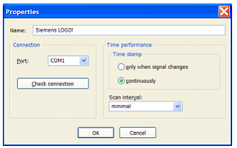
Installation of PLC Driver Siemens LOGO!


The PLC driver can be installed while PLC-ANALYZER pro is operating. Select the PLC driver in menu Extras. In the widow PLC driver click the button Add. If the desired driver is not on the list, you have to install a new driver via the License-Key management.

With PLC-ANALYZER pro you can load the same or different PLC driver more than once to acquire data from different PLC.

Installing Additional Hardware
If you have connected your PC with LOGO! Using LOGO! (USB) PC cable, usually nothing else must be done.

Installing Additional Software
No software is required in addition to the PLC-ANALYZER pro basic module and the PLC driver.

Configuration of PLC Driver
After installing the driver you can change important parameters under Properties.
Configuration of PLC Driver
Choose meaningful name for the driver first, and then specify under Connection the Com-Port of the PLC, which is connected by a cable to the PLC. Press Test Connection to check whether a connection to the PLC can be established.

Use Time Stamp to specify, if the time stamps should be entered into the signal file continually or only signal changes. For a continuous time stamp the exact scan points are documented even for a signal which does not change.

Under Scan Interval enter the length of time between read-out of data from the PLC. A longer scan interval may be chosen for non critical time signals.

The Benefits of Conversion RS Logix 500 to RS Logix 5000


The conversion programming from RS Logix 500 to RS Logix 5000 seen versatility alone could make the conversion from the RS Logix 500 platform to the RS Logix 5000 platform a worthwhile venture. With four different programming languages at your disposal, almost every electro-mechanical control application conceivable can be accomplished through the implementation of Rockwell Software’s RS Logix 5000 software.

Due to the multiple programming languages, it was able to be shortened. Each programming language has a topic that it has been designed for. With this in mind, the Ladder logic pertaining to the heating zones was more suitable for function block diagrams than Ladder logic. The commands are more suitable to particular applications, therefore, shortened the code.

Another benefit is having the ability to program all inputs and outputs using descriptive tags. It was obvious through the project code writing processes that a program with tags would make a program not only easier to follow, but easier to troubleshoot too. Additionally, the ability to monitor and change tag values, while the program is online, has been a benefit. For example, gain values for a PIDE function block can be changed online to optimize your PIDE curve. The result of this tuning can be seen almost instantaneously and will not disrupt the other program functions.

Timer Countdown with PLC Keyence


PLC Type KV-40 Keyence , Name Input / Output PLC :

INPUT PLC :
0000 ; Toggle Switch ( ON - OFF ).

OUTPUT PLC :
0500 ; OUT0 or Seven Segment A of Digit 1.
0501 ; OUT1 or Seven Segment B of Digit 1.
0502 ; OUT2 or Seven Segment C of Digit 1.
0503 ; OUT3 or Seven Segment D of Digit 1.
0504 ; OUT4 or Seven Segment E of Digit 1.
0505 ; OUT5 or Seven Segment F of Digit 1.
0506 ; OUT6 or Seven Segment G of Digit 1.
0507 ; OUT7 or Seven Segment A of Digit 2.
0508 ; OUT8 or Seven Segment B of Digit 2.
0509 ; OUT9 or Seven Segment C of Digit 2.
0510 ; OUT10 or Seven Segment D of Digit 2.
0511 ; OUT11 or Seven Segment E of Digit 2.
0512 ; OUT12 or Seven Segment F of Digit 2.
0513 ; OUT12 or Seven Segment G of Digit 2.
0514 ; Lamp to signal countdown completion.

PLC Programming for Timer Countdown with PLC Keyence


Reading Ladder PLC Programming for Timer Countdown with PLC Keyence :

Step 1 :
Setting Timer T000 = 1 Second
Decrements the memory data specified by the operand by 1
a.If 0000 = ON And 1200 = OFF And T000 = ON Then Decrement DM0000 ( @DEC / Decrement diff.Up).

Step 2 :
a.If 0000 = OFF Then DM0000 = 30 ( DW #00030 DM0000 ).
b.If DM0000 = 0 Then 1200 = ON And 0514 = ON.

Step 3 : Determine digit1 and digit2
Digit1 : 0 -- 1 -- 2 -- 3 -- 4 -- 5 -- 6 -- 7 -- 8 -- 9
Digit2 : 00 -- 10 -- 20 -- 30 -- 40 -- 50 -- 60 -- 70 -- 80 -- 90
a.Load DM0000 to Accumulator (LDA DM0000) --> Convert to BCD (TBCD) --> AND with Hexa 000F (ANDA $000F) --> Convert to Binary (TBIN) --> Store to DM0001.
b.Load DM0000 to Accumulator (LDA DM0000) --> Convert to BCD (TBCD) --> AND with Hexa 00F0 (ANDA $00F0) --> Convert to Binary (TBIN) --> Store to DM0002.

Example : Value DM0000 = 29
-->If DM0000 = 29 Then DM0001 = 9 And DM0002 = 20.

Step 4 : digit1
a.If DM0001 = 0 Then 1000 = ON.
b.If DM0001 = 1 Then 1001 = ON.
c.If DM0001 = 2 Then 1002 = ON.
d.If DM0001 = 3 Then 1003 = ON.
e.If DM0001 = 4 Then 1004 = ON.
f.If DM0001 = 5 Then 1005 = ON.
g.If DM0001 = 6 Then 1006 = ON.
h.If DM0001 = 7 Then 1007 = ON.
i.If DM0001 = 8 Then 1008 = ON.
j.If DM0001 = 9 Then 1009 = ON.

Step 5 : digit2
a.If DM0002 = 00 Then 1100 = ON.
b.If DM0002 = 10 Then 1101 = ON.
c.If DM0002 = 20 Then 1102 = ON.
d.If DM0002 = 30 Then 1103 = ON.
e.If DM0002 = 40 Then 1104 = ON.
f.If DM0002 = 50 Then 1105 = ON.
g.If DM0002 = 60 Then 1106 = ON.
h.If DM0002 = 70 Then 1107 = ON.
i.If DM0002 = 80 Then 1108 = ON.
j.If DM0002 = 90 Then 1109 = ON.

Step 6 : Output digit1
a.If 1000 = ON Then 0500 = ON And 0501 = ON And 0502 = ON And 0503 = ON And 0504 = ON And 0505 = ON.
b.If 1001 = ON Then 0501 = ON And 0502 = ON.
c.If 1002 = ON Then 0500 = ON And 0501 = ON And 0503 = ON And 0504 = ON And 0506 = ON.
d.If 1003 = ON Then 0500 = ON And 0501 = ON And 0502 = ON And 0503 = ON And 0506 = ON.
e.If 1004 = ON Then 0501 = ON And 0502 = ON And 0505 = ON And 0506 = ON.
f.If 1005 = ON Then 0500 = ON And 0502 = ON And 0503 = ON And 0505 = ON And 0506 = ON.
g.If 1006 = ON Then 0500 = ON And 0502 = ON And 0503 = ON And 0504 = ON And 0505 = ON And 0506 = ON.
h.If 1007 = ON Then 0500 = ON And 0501 = ON And 0502 = ON.
i.If 1008 = ON Then 0500 = ON And 0501 = ON And 0502 = ON And 0503 = ON And 0504 = ON And 0505 = ON And 0506 = ON.
j.If 1009 = ON Then 0500 = ON And 0501 = ON And 0502 = ON And 0503 = ON And 0505 = ON And 0506 = ON.

Step 7 : Output digit2
a.If 1100 = ON Then 0507 = ON And 0508 = ON And 0509 = ON And 0510 = ON And 0511 = ON And 0512 = ON.
b.If 1101 = ON Then 0508 = ON And 0509 = ON.
c.If 1102 = ON Then 0507 = ON And 0508 = ON And 0510 = ON And 0511 = ON And 0513 = ON.
d.If 1103 = ON Then 0507 = ON And 0508 = ON And 0509 = ON And 0510 = ON And 0513 = ON.
e.If 1104 = ON Then 0508 = ON And 0509 = ON And 0512 = ON And 0513 = ON.
f.If 1105 = ON Then 0507 = ON And 0509 = ON And 0510 = ON And 0512 = ON And 0513 = ON.
g.If 1106 = ON Then 0507 = ON And 0509 = ON And 0510 = ON And 0511 = ON And 0512 = ON And 0513 = ON.
h.If 1107 = ON Then 0507 = ON And 0508 = ON And 0509 = ON.
i.If 1108 = ON Then 0507 = ON And 0508 = ON And 0509 = ON And 0510 = ON And 0511 = ON And 0512 = ON And 0513 = ON.
j.If 1109 = ON Then 0507 = ON And 0508 = ON And 0509 = ON And 0510 = ON And 0512 = ON And 0513 = ON.

Please Download Programming for KV Builder :
Timer Countdown with PLC Keyence

See : Timer Countdown

Set Up EthernetIP for ControlLogix 5000


EDS file is an Ethernet IP EDS file specific to PumpSmart PS200 is available on the PS200 v5 Fieldbus Communications web page. Note that EDS files are only required when using RSNetworx for Ethernet in your application. This example is not using RSNetworx for Ethernet but is opening a generic Ethernet module in the ControlLogix 5000 PLC.

1. Open RS Logix 5000 and open an RSLogix 5000 program. Right click on the 1769-L32E Ethernet Port Local ENB.
RSLogix 5000 program
2. Click on new Module.
RSLogix 5000 new Module
3. Select module Ethernet – Module
RSLogix 5000 module Ethernet
4. Program the following information below. The example below is using Input and Output Assembly instances 102 and 103. Once completed click finish.
RSLogix 5000 Input and Output
Input and Output sizes must match that used in the PS200. If writing to the Control Word and first reference, and reading the status word, motor speed, power, and smart flow, the output size must be 2 and the input size must be 4.

5. The RETA-01 is now added to the PLC I/O.
RETA-01 added PLC I/O
The problem or error that usually happened is unable to establish communications between the drive and the DCS (PLC). To avoid this problem:
• Be sure the module is located in slot 1 of the PS200.
• Check the MAC Addressing between the DCS and the drive specifically the IP and Subnet Mask.
• Be sure the Comm Rate and DHCP values are correct for the network.
• Be sure that parameter 31.01 state RETA-01.
• Be sure that you have refreshed the fieldbus module anytime after you change parameters in group 31.27.
Sponsored Links :

ALL ARTICLES
SUBSCRIBE BY EMAIL:

Delivered by FeedBurner


PLC Simulation Update

Popular Posts

Free Download PLC

Custom Search
Copyright © PLC Ladder